Cementing compositions and the use of such compositions for cementing wells
a technology of compositions and cementing wells, applied in the direction of sealing/packing, borehole/well accessories, sustainable waste treatment, etc., can solve the problems of increasing shock resistance, reducing the compressibility of the system, and reducing the permeability, so as to improve the impact strength, the effect of low density and low permeability
- Summary
- Abstract
- Description
- Claims
- Application Information
AI Technical Summary
Benefits of technology
Problems solved by technology
Method used
Image
Examples
example 1
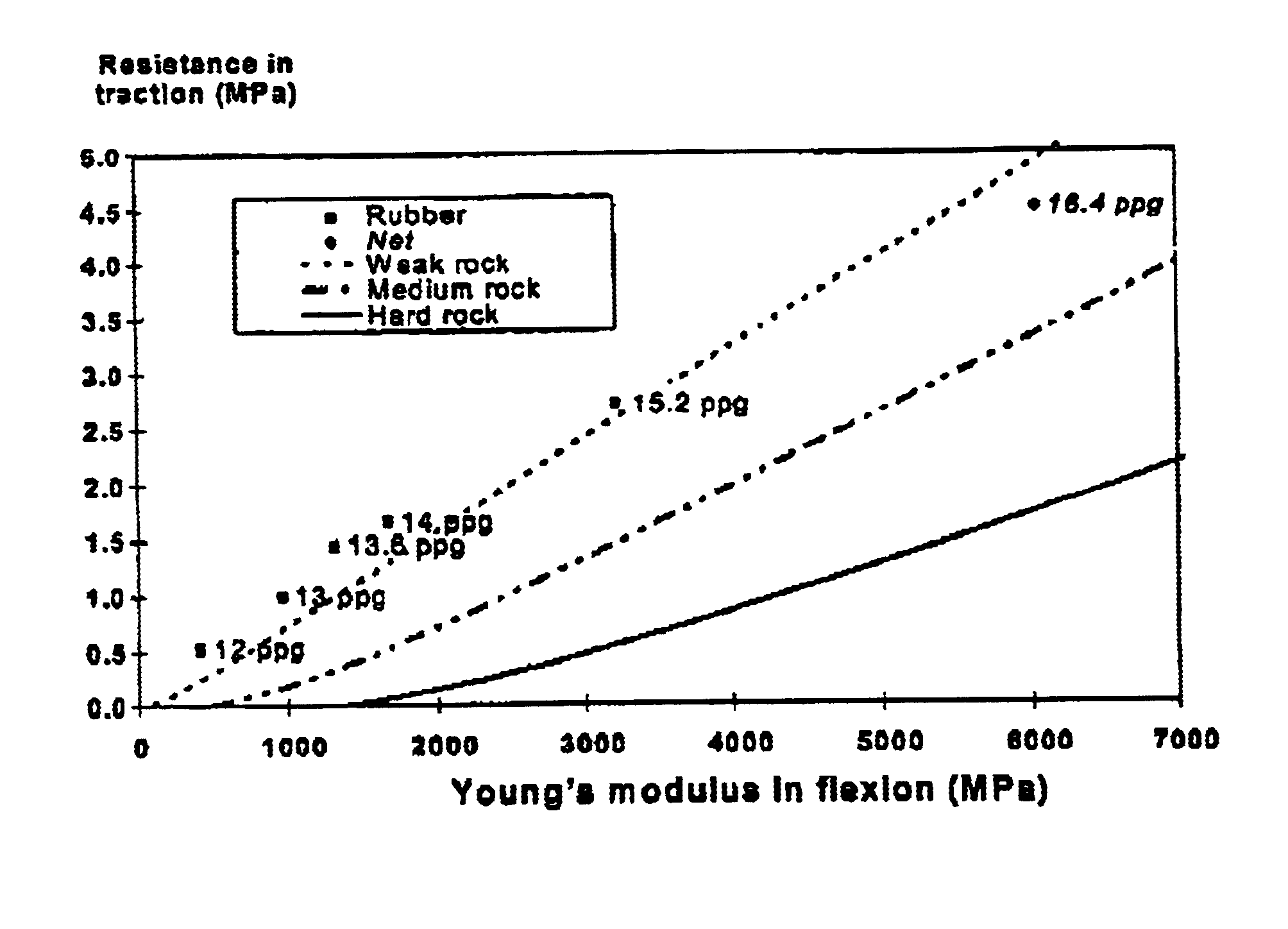
[0027]Non optimized formulations were used to show the basic principle of the invention. With the exception of a dispersing agent, they did not include cementing additives. In this example, the recycled rubber originated from American Tire Recyclers, Inc., Jacksonville, United States of America. Its trade name is “Ground Rubber 40 mesh”. Its density was 1.2 g / cm3, and its granulometry was 40 mesh (425 μm).
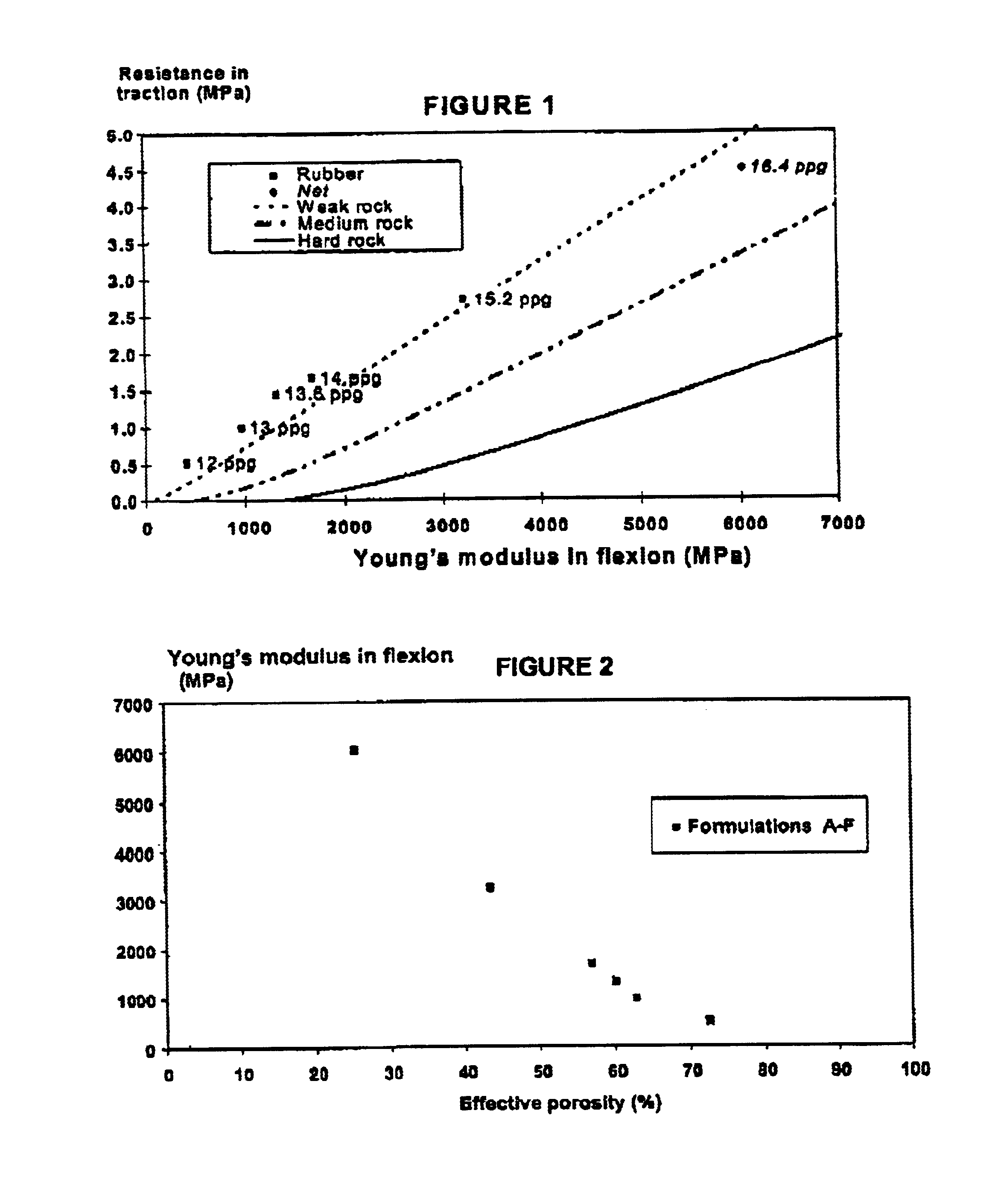
[0028]The cement slurries were composed of class G Portland Dyckerhoff North cement, recycled rubber particles, water, and a dispersing agent. The formulations are given in Table 1; they were all studied at the same temperature (170° F., i.e., 76.7° C.). The dispersing agent was a polynaphthalene sulfonate, in liquid form.
[0029]
TABLE 1Cement slurry formulationsOther additives(=dispersingDensityWaterRubberCementagents)Formulation(ppg-g / cm3)(vol %)(vol %)(vol %)vol %A12.0-1.4450.032.517.50B13.1-1.5655.020.224.80C13.6-1.6349.922.527.50.1D14.1-1.6944.724.730.30.3E15.2-1.8249.612.537.50...
example 2
[0049]Examples of complete formulations are given.
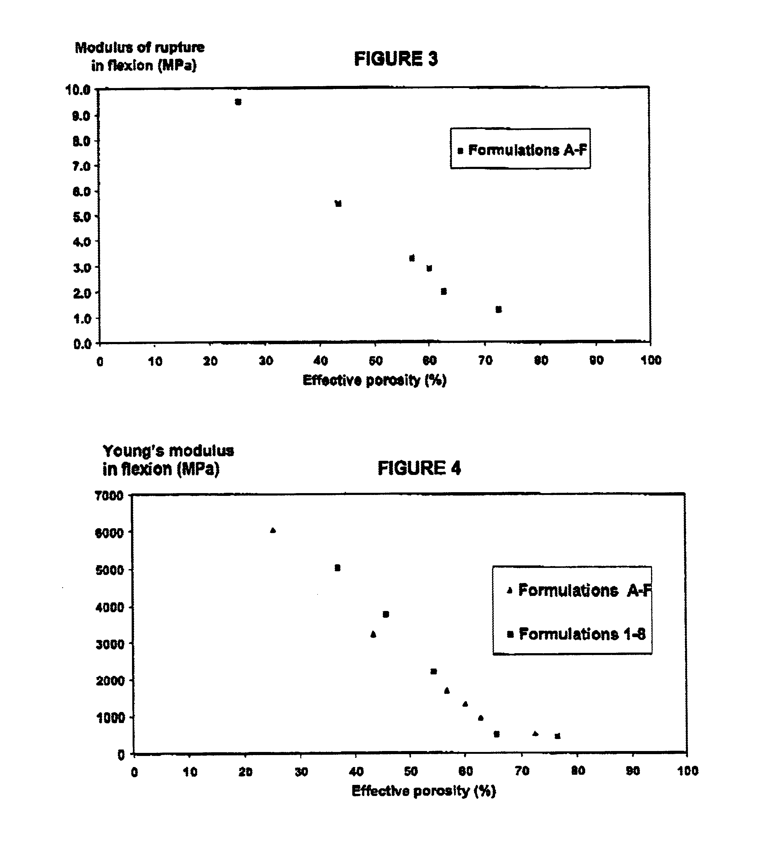
[0050]The cement slurries were composed of class G Portland Dyckerhoff North cement, recycled rubber particles, water and different additives (anti-foaming agent and retarder; the retarder was different depending on the temperature). Table 5 lists the formulations. Formulations 1 and 7 contained no rubber particles. Formulations 2 to 5 comprised 40 mesh rubber identical to that of the preceding example. Formulation 6 used a 45 mesh (355 μm) rubber available from Vredenstein Rubber Resources, Maastricht, Netherlands reference ECORR RNM 45, density 1.2 g / cm3.
[0051]The influence of parameters such as slurry density and the optimization temperature were studied. For temperatures of 120° C. or more, silica flour was used for retrocession strength problems.
[0052]It is important to dry blend the rubber particles with the cement. Otherwise, poor incorporation or migration of the rubber to the surface after mixing is observed.
[0053]
TABLE 5LIS...
example 3
[0058]Ground rubber particles of 32 mesh grain size (500 μm) were tested.
[0059]In this example, two slurry formulations were used as already described in the preceding examples: formulation D of Example 1, and formulation 2 of Example 2; they were both formulated to 14 ppg (1.68 g / cm3) with a slurry porosity of 45% and comprised 30% bwoc of rubber particles. The only change was in the rubber particles which differed in their manufacturer and in their grain size, the 32 (500 μm) mesh sized grains replacing the 40 (425 μm) mesh sized grains.
[0060]Formulation D with the new source of rubber was not API mixable, and a portion of the rubber remained on the surface. This phenomenon persisted even if, for example, the added concentration of dispersing agent (a polynaphthalene sulfate) was multiplied by 2.
[0061]Regarding formulation 2, it was observed that the slurry was a poor API mix and that after conditioning, the cement slurry was very thick and cast badly. To reduce its viscosity by l...
PUM
| Property | Measurement | Unit |
|---|---|---|
| Grain size | aaaaa | aaaaa |
| Grain size | aaaaa | aaaaa |
| Fraction | aaaaa | aaaaa |
Abstract
Description
Claims
Application Information
 - R&D
- Intellectual Property
- Life Sciences
- Materials
- Tech Scout
- Unparalleled Data Quality
- Higher Quality Content
- 60% Fewer Hallucinations
Browse by: Latest US Patents, China's latest patents, Technical Efficacy Thesaurus, Application Domain, Technology Topic, Popular Technical Reports.
© 2025 PatSnap. All rights reserved.Legal|Privacy policy|Modern Slavery Act Transparency Statement|Sitemap|About US| Contact US: help@patsnap.com


