Optical connector plug, optical connector adapter and optical connector

a technology of optical connectors and adapters, applied in the direction of optics, printed circuits, instruments, etc., can solve the problems of large number of parts, restricting the use of optical connectors, complicated steps, etc., and achieves the effects of reducing manufacturing costs, simplifying the integration step, and promoting reliability

Inactive Publication Date: 2005-06-21
SEIKOH GIKEN
View PDF3 Cites 46 Cited by
  • Summary
  • Abstract
  • Description
  • Claims
  • Application Information

AI Technical Summary

Benefits of technology

[0022]It is an object of the invention to provide an optical connector which promotes reliability by reducing insertion loss of an optical fiber and which is downsized.
[0036]According to a fourteenth aspect of the invention, there is provided the optical connector according to any one of the ninth through the thirteenth aspects, wherein an inner side of an outer edge of an opening of the sleeve inserting hole is provided with a projection of the sleeve brought into contact with an outer peripheral face of the sleeve for optical connection for preventing detachment from the sleeve inserting hole.
[0045]According to the invention, fabrication cost can be reduced and an integrating step can be simplified by reducing a number of parts of the optical connector comprising the optical connector plug and the optical connector adapter. Further, the reliability can be promoted without restricting a number of times of attachment and detachment of the optical connector plug and the optical connector adapter and without damaging a front end face of the optical fiber. Further, by providing the mounting member attachable and detachable to and from the optical connector adapter at the optical connector, it is not necessary to attach and detach the optical connector adapter and the optical connector plug on the mounting board and the mounting board can be downsized.

Problems solved by technology

According to the optical connection of the optical fibers achieved by a welding process, there a problem that attachment and detachment of the optical connection of the optical fibers cannot be carried out and a problem that the welding steps are complicated, thereby restricting the use of the optical connector.
Therefore, a number of parts is large and downsizing thereof is difficult.
Therefore, a wide mounting are is needed for mounting a comparatively small-sized MU type optical connector at a mounting board and there poses a problem that downsizing of the mounting board per se cannot be achieved.
Further, when the optical connector of the related art is mounted to the mounting board, the optical adapter is directly fixed to the mounting board and therefore, a space for attaching and detaching the optical connector plug holding the optical fiber is needed on the mounting board and there poses a problem that not only the mounting board is large-sized but also operational efficiency is poor.
Further, there is a problem that the conventional optical connector has a large number of parts and that integration of the optical connector flag and the optical connector adapter of the conventional optical connector is difficult to achieve.
However, according to the above-described optical connector using the leaf spring, there poses a problem that owing to durability performance of the leaf spring, when attachment and detachment are repeated, durability of the leaf spring is deteriorated, a deterioration in opposing connection of optical fibers, that is, a deterioration in insertion loss is brought about and therefore, a number of times of attachment and detachment is restricted.
Further, according to the above-described optical connector using the leaf spring, since there is no means for restricting movement of the ferrule holding the front end of the optical fiber in a rotating direction centering on an axis thereof, an eccentric direction of the core of the optical fiber cannot be prescribed and the inserting loss is increased by bringing about an eccentric shift of the core.
Further, according to the above-described optical connector using the leaf spring, there poses a problem that the ferrule is liable to disengage from the leaf spring by vibration and impact and the reliability is poor.
Further, according to the above-described optical connector using the leaf spring, the front end portion of the cylindrical body for ferrule is directly inserted into a sleeve for optical connection and therefore, there poses a problem that a defect is liable to be brought about at the polished front end face of the cylindrical member for ferrule when an inserting angle is large or by repeating attachment and detachment, the inserting loss in optical connection is liable to increase and the reliability is poor.

Method used


Image

  • Optical connector plug, optical connector adapter and optical connector
  • Optical connector plug, optical connector adapter and optical connector
  • Optical connector plug, optical connector adapter and optical connector

Examples


embodiment 1

[0064](Embodiment 1)

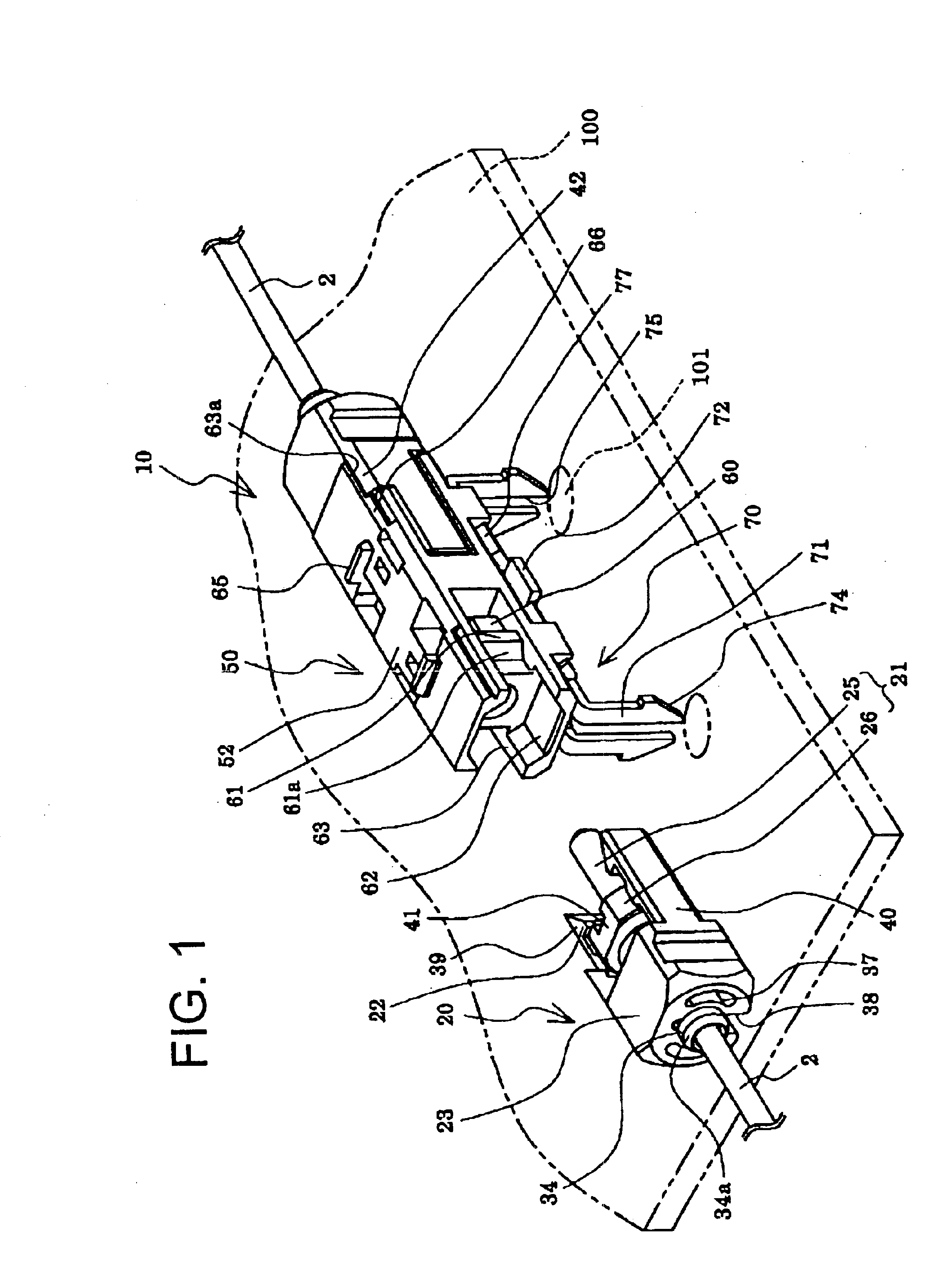
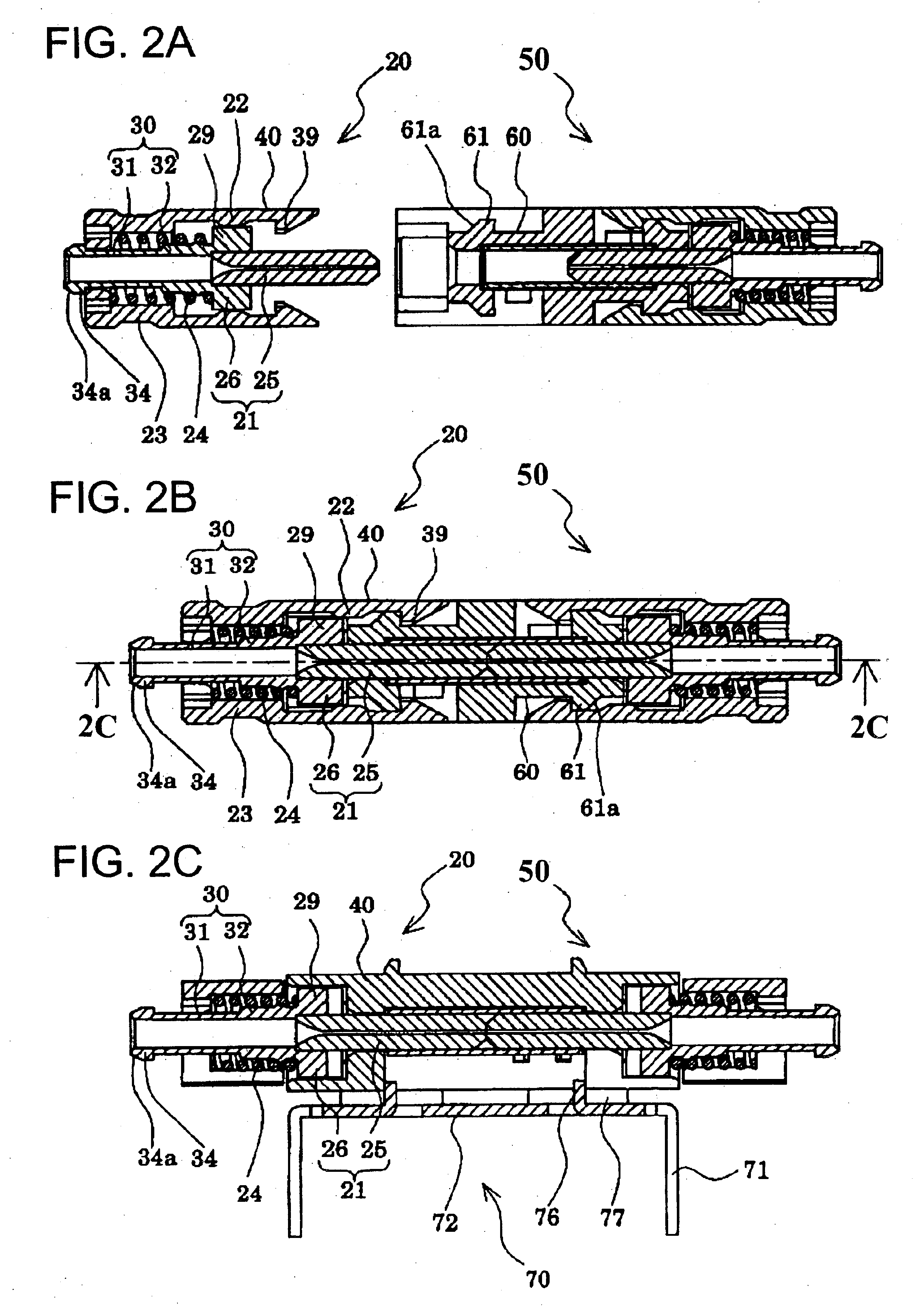
[0065]FIG. 1 is a perspective view showing a step of mounting an optical connector according to Embodiment 1, FIG. 2A is a sectional view showing a step of connecting the optical connector, FIG. 2B is a sectional view showing a state of connecting the optical connector, FIG. 2C is a sectional view taken along a line 2C—2C of FIG. 2B, FIGS. 3A and 3B are plane views of an optical connector plug, FIG. 3C is a sectional view taken along a line 3C—3C of FIG. 3A and FIG. 4 is a plane view showing a step of integrating the optical connector plug.

[0066]As illustrated, an optical connector jig 10 comprises an optical connector plug 20, an optical connector adapter 50 and a mounting member 70.

[0067]The optical connector plug 20 is constituted by a ferrule 21 for holding an optical fiber 1, a plug housing 23 for directly holding the ferrule 21 movably in an axial direction in a predetermined range and provided with a first rotation stopper portion 22 for restricting moveme...

embodiment 2

[0169

[0170]FIG. 10 is a perspective view showing a step of mounting to laminate optical connectors according to Embodiment 2 and FIG. 11 is a perspective showing a state of mounting to laminate optical connecters according to Embodiment 2. Further, members similar to those of Embodiment 1, mentioned above, are attached with the same notations and duplicated explanation thereof will be omitted.

[0171]As shown by FIG. 10 and FIG. 11, an optical connector 10A is provided with the optical connector plug 20, an optical connector adapter 50A and a mounting member 70A.

[0172]The mounting member 70A comprises the bent portion 71 and a base seat portion 72A and adapter engaging portions 77A are provided at edge portions on both sides in a width direction of the base seat portion 72A.

[0173]The adapter engaging portions 77A are formed to bend to project to a side opposed to the bent portion 71 and formed such that front end portions thereof are bent to both sides in the width direction to consti...

embodiment 3

[0180

[0181]FIG. 12 is a perspective view showing a step of integrating an optical connector adapter according to Embodiment 3 and FIGS. 13A and 13B are a plane view of the optical connector adapter and a sectional view taken along a line 13B—13B thereof. Further, members similar to those of Embodiments 1 and 2, mentioned above, are attached with the same notations and a duplicated explanation thereof will be omitted.

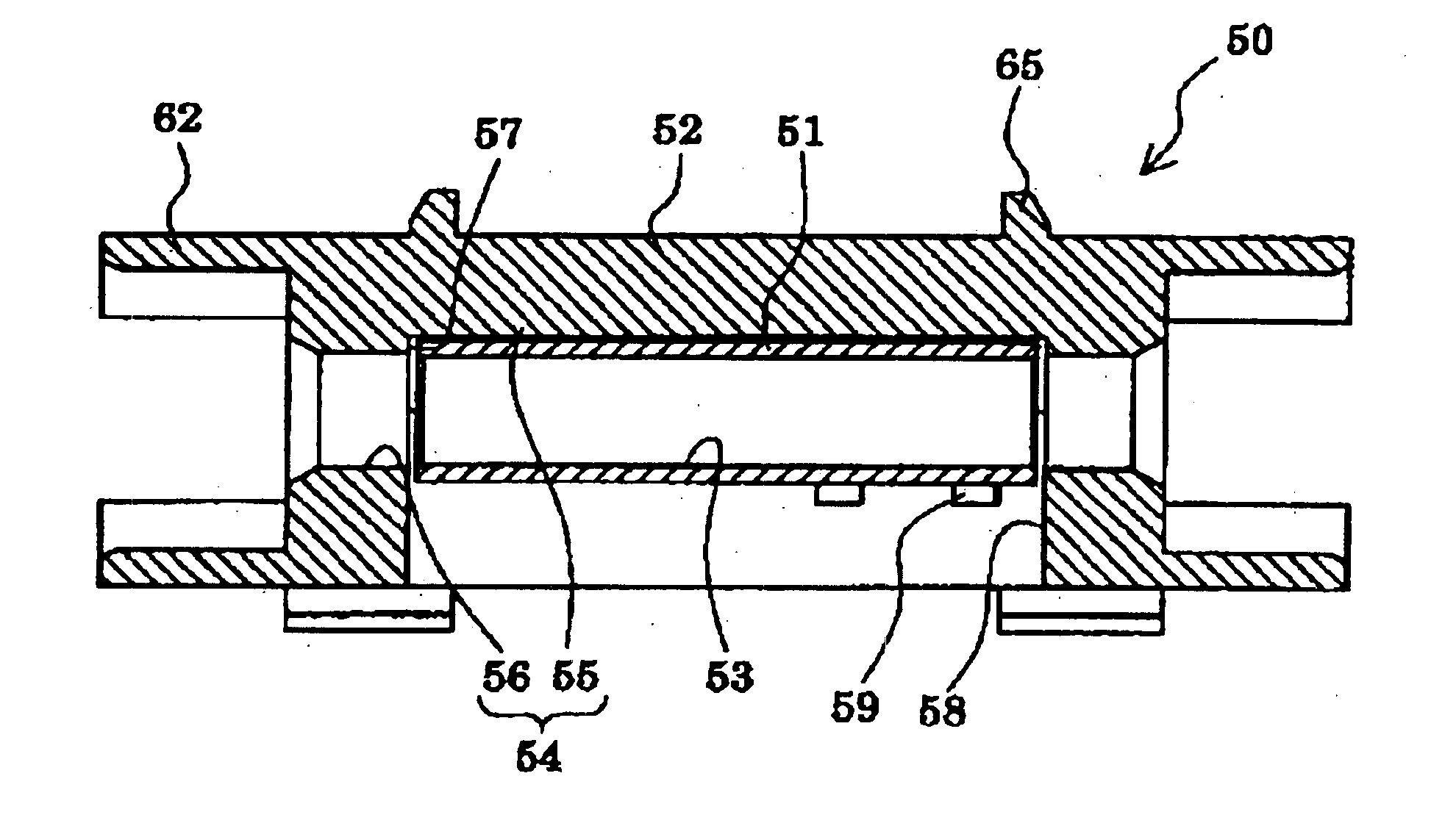
[0182]As shown by FIG. 12 and FIGS. 13A and 13B, an optical connector adapter 50B of the embodiment is provided with the sleeve for optical connection 51 inserted with a front end portion of a cylindrical member for ferrule and an adapter housing 52B including the sleeve for optical connection 51 and an adapter housing 52B and is constituted by a housing main body 110 provided with a sleeve inserting hole 58B inserted with the sleeve for optical connection 51 and opened at one face thereof and a lid member 120 fitted to the sleeve inserting hole 58B of the housing main b...


PUM


Abstract

To provide an optical connector promoting reliability by reducing insertion loss of an optical fiber and downsized, there is provided an optical connector plug having a ferrule including a cylindrical member for the ferrule for holding an optical fiber and a flange member provided at a rear end portion of the cylindrical member for the ferrule, an urge spring provided on a side of a rear end portion of the flange member of the ferrule, and a plug housing for holding the ferrule and the urge spring directly at inside thereof and directly engaged with an optical connector adapter inserted with a front end portion of the ferrule to carry out optical connection, in which the plug housing is formed with a slit capable of inserting the optical fiber in a radius direction thereof at a portion of an outer periphery thereof over an axial direction.

Description

BACKGROUND OF THE INVENTION[0001]1. Field of the Invention[0002]The present invention relates to an optical connector plug and an optical connector adapter as well as an optical connector for holding a front end of an optical fiber and optically connecting the optical fibers.[0003]2. Description of the Related Art[0004]In a related art, optical connection of optical fibers used in optical communication is carried out by a method of using an optical connector having an optical connector plug holding a front end of the optical fiber and an optical connector adapter for carrying out optical connection of the optical fibers by fixing the optical connector plugs, or a method of welding front end faces of the optical fibers.[0005]According to the optical connection of the optical fibers achieved by a welding process, there a problem that attachment and detachment of the optical connection of the optical fibers cannot be carried out and a problem that the welding steps are complicated, the...

Claims


Application Information

Patent Timeline
Patent Type & Authority Patents(United States)
IPC IPC(8): G02B6/38
CPCG02B6/3807G02B6/3825G02B6/3898G02B6/3879G02B6/3897G02B6/3877G02B6/3821G02B6/3893
Inventor NAKAJIMA, MASAHIROMINAMI, KOUJITAIRA, JUNJI
Owner SEIKOH GIKEN
Why Eureka
Try Eureka