Axial flow fan

a technology of axial flow and fan, which is applied in the direction of chairs, other chemical processes, vessel construction, etc., can solve the problems of degrading the desired quiet running of the motor vehicle, unable to provide a unable to achieve satisfactory noise reduction effect, so as to achieve the effect of reducing the blowing nois

Inactive Publication Date: 2005-06-21
HANON SYST
View PDF6 Cites 28 Cited by
  • Summary
  • Abstract
  • Description
  • Claims
  • Application Information

AI Technical Summary

Benefits of technology

[0031]The axial flow fan having the above described configuration according to the present invention achieves reduction of blowing noise by receiving air in a dispersed state at the leading edge of ...

Problems solved by technology

Although the conventional axial flow fans have the above mentioned forward or backward-swept blade structures, they cannot provide a satisfactory noise reduction effect.
Although the conventional axial flow fans respectively having the above menti...

Method used


Image

  • Axial flow fan
  • Axial flow fan
  • Axial flow fan

Examples


Embodiment Construction

[0046]Now, preferred embodiments of the present invention will be described in detail with reference to the attached drawings.

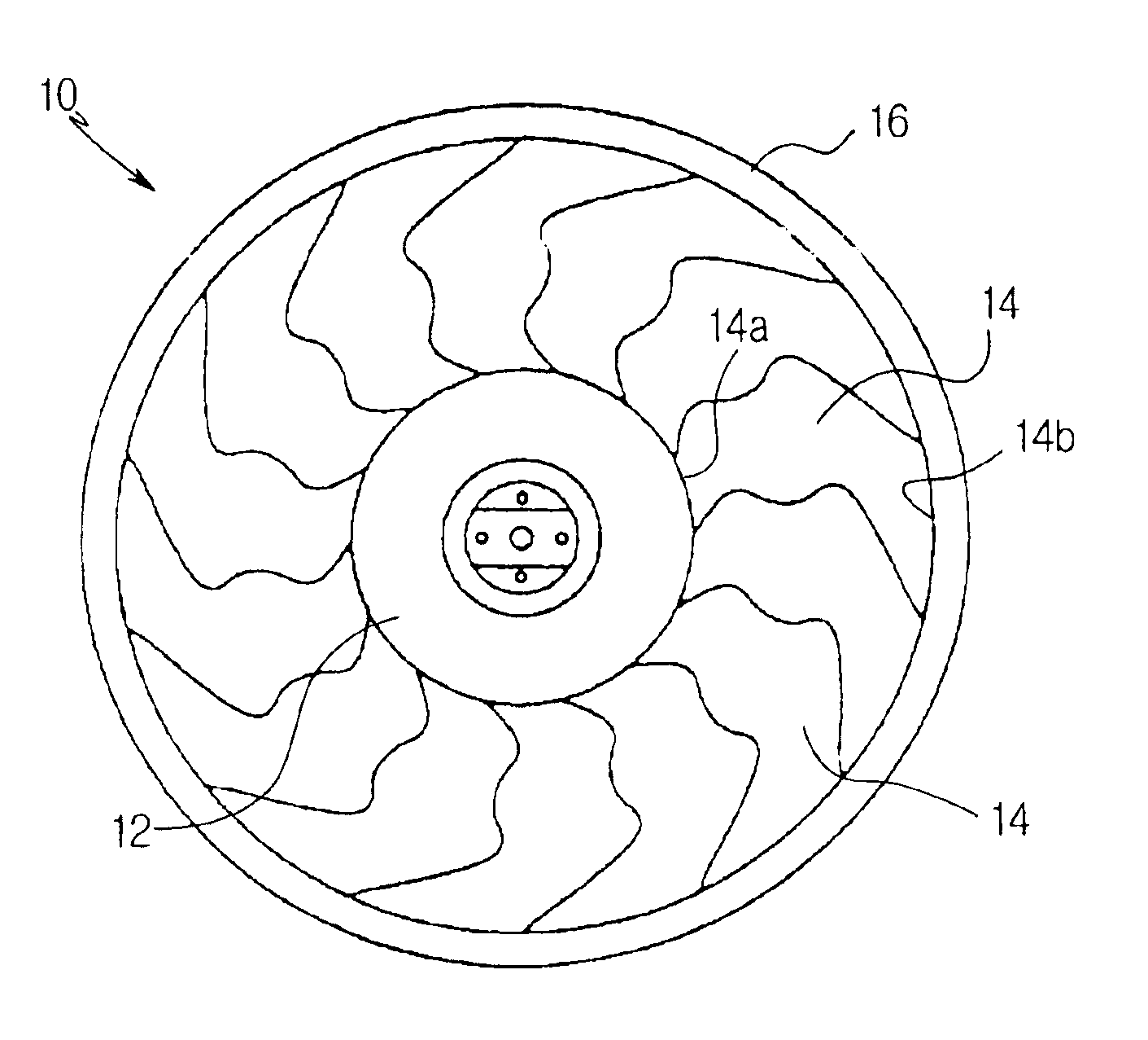
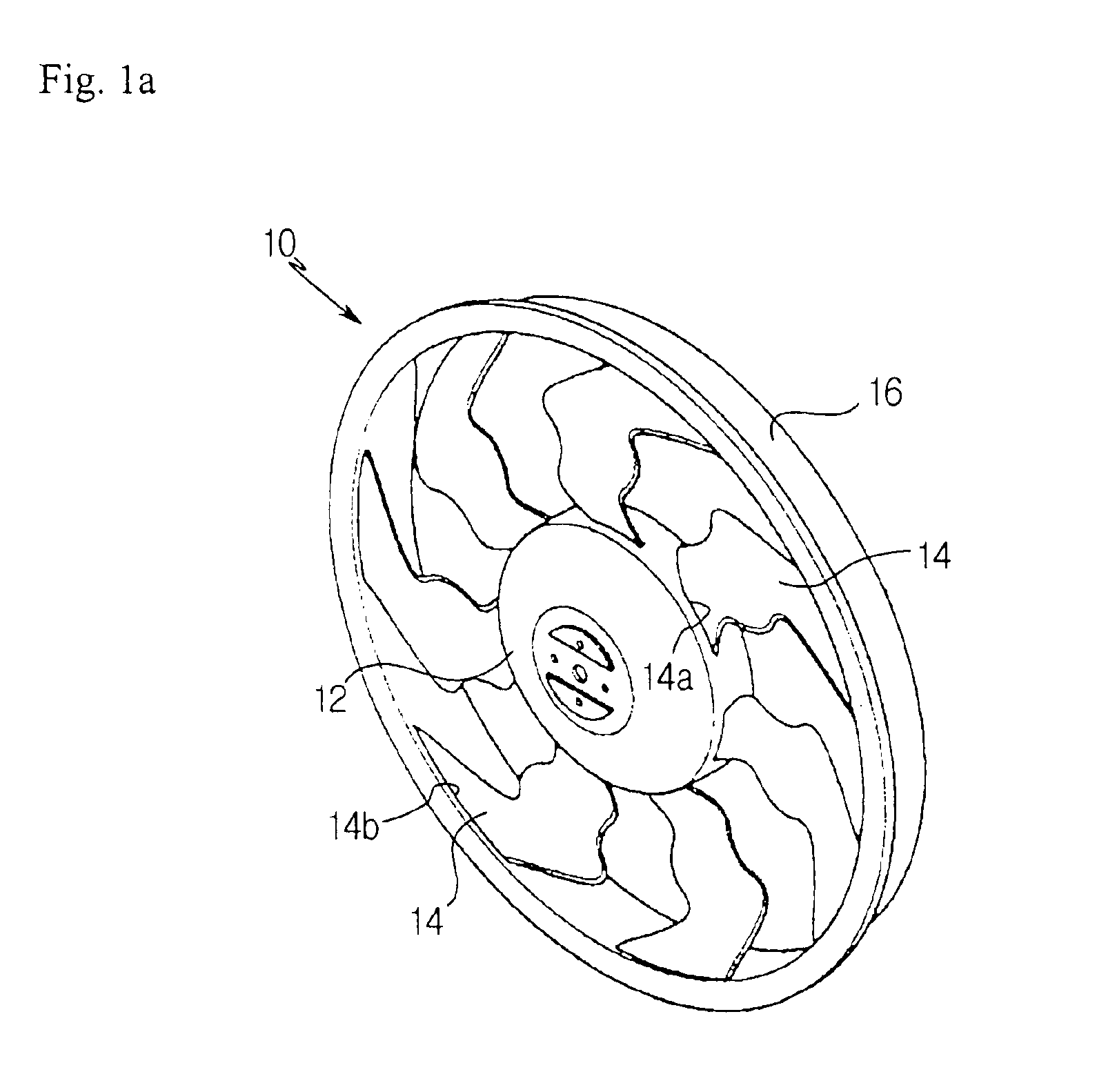
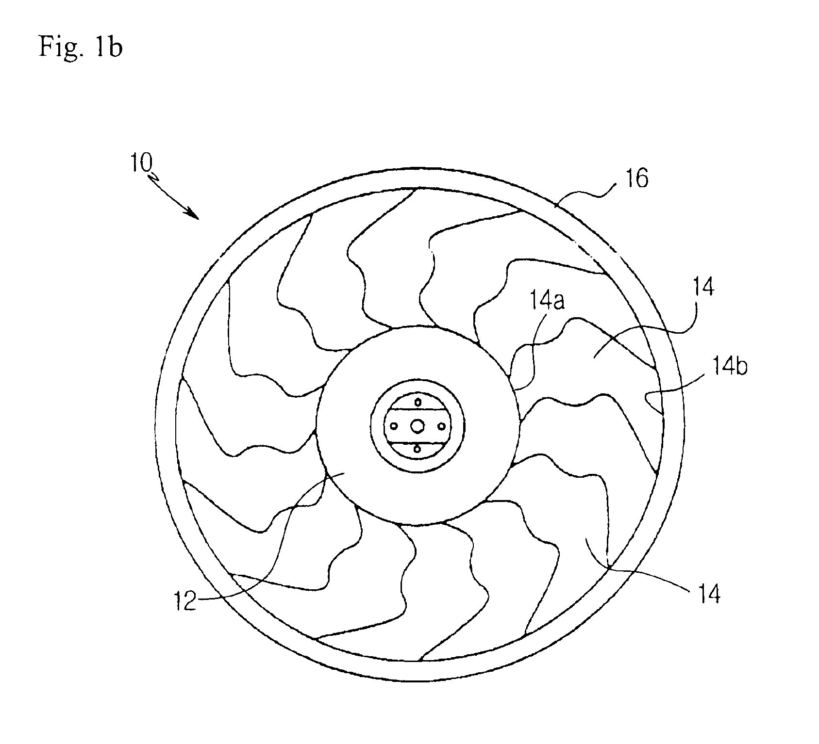
[0047]Axial flow fans according to the present invention are illustrated in FIGS. 1a and 1b, and FIGS. 2a and 2b. In either case of FIGS. 1a and 1b or FIGS. 2a and 2b, the axial flow fan, which is denoted by the reference numeral 10, includes a hub 12 coupled to the shaft of a motor (not shown), and a plurality of blades 14 extending radially around the hub 12. In the case illustrated in FIGS. 1a and 1b, the axial flow fan 10 includes 7 blades 14. In the case illustrated in FIG. 2a, the axial flow fan 10 includes 4 blades 14.

[0048]The axial flow fan 10 of the present invention may further include an annular fan band 16 surrounding the blades 14 while connecting tips 14b of the blades 14 together.

[0049]As shown in FIGS. 1c, 1d, and 2c, each blade 14 of the axial flow of the axial flow fan 10 has a sweep angle σr, that is, an angle formed between a tangent line...


PUM


Abstract

Disclosed is an axial flow fan capable of achieving reduction of noise while having a high blowing efficiency compared to the power consumption of a motor adapted to drive the axial flow fan. The axial flow fan includes a hub, and a plurality of blades extending radially around the hub. Each blade has a sweep angle varying gradually from a backward angle at a root of the blade connected to the hub to a forward angle at a tip of the blade, while having a flow dispersion region having a plurality of regions where the sweep angle is alternately changed, at a region defined between a backward sweep angle region at the root of the blade and a forward sweep angle region at the tip of the blade. Each blade has a longitudinal cross section curved to have a wave structure between the root of the blade and the tip of the blade. The axial flow fan may further include a fan band connecting tips of the blades. The axial flow fan achieves reduction of blowing noise by receiving air in a dispersed state at the leading edge of each blade, discharging air in a dispersed state at the trailing edge of each blade, and offsetting turbulent flows of air by virtue of the wave-shaped longitudinal cross-sectional structure of each blade.

Description

BACKGROUND OF THE INVENTION[0001]1. Field of the Invention[0002]The present invention relates to an axial flow fan for axially moving air, and more particularly to an axial flow fan capable of achieving reduction of noise while having a high blowing efficiency compared to the power consumption of a motor adapted to drive the axial flow fan.[0003]2. Description of the Related Art[0004]Generally, axial flow fans are configured to axially move air while rotating in accordance with the driving operation of a drive motor. Such an axial flow fan may be effectively used in motor vehicles to promote heat discharge of a heat exchanger such as a radiator or condenser.[0005]Referring to FIGS. 7 and 8, an axial flow fan for a motor vehicle is illustrated. As shown in FIGS. 7 and 8, this axial flow fan includes a hub 1 coupled to the drive shaft of a drive motor, and a plurality of blades 2 extending radially around the hub 1. The axial flow fan for motor vehicles may also selectively include an...

Claims


Application Information

Patent Timeline
IPC IPC(8): F04D29/32F04D29/38F04D29/66
CPCF04D29/326F04D29/384Y10S416/05Y10S416/02
Inventor CHO, KYUNG SEOKMIN, OK RYULPARK, CHANG HO
Owner HANON SYST
Why Eureka
Try Eureka