Cooling system for dynamoelectric machine

a technology of dynamoelectric machines and cooling systems, which is applied in the direction of cooling/ventilation arrangement, magnetic circuit shape/form/construction, association for rectification, etc., can solve the problems of reducing efficiency or damage to components such as windings and bearings, limiting the space available for cooling passages, and particularly challenging cooling for a relatively small or compact machine. , to achieve the effect of reducing the drop of coolant pressure and small in siz

Active Publication Date: 2005-06-21
NIDEC SR DRIVES
View PDF39 Cites 97 Cited by
  • Summary
  • Abstract
  • Description
  • Claims
  • Application Information

AI Technical Summary

Benefits of technology

[0005]Among the several objects and features of the present invention may be noted the provision of a dynamoelectric machine having a cooling system for removing heat from the machine; the provision of such a machine wherein the cooling system cools uniformly about the machine; the provision of such a machine and cooling system wherein the coolant pressure

Problems solved by technology

Dynamoelectric machines such as electric motors generate heat during operation which may degrade efficiency or damage component parts, such as windings and bearings.
Cooling is particularly challenging for a relatively small or compact machine, such as an integrated starter generator for an automotive vehicle.
That machine must be packaged so that it occupies only a relatively small space in a vehicle engine compartment (e.g., maximum length and diameter dimensions of about six inches), which limits the amount of space available to accommodate coolant passages.
Prior cooling jackets have suffered from v

Method used


Image

  • Cooling system for dynamoelectric machine
  • Cooling system for dynamoelectric machine
  • Cooling system for dynamoelectric machine

Examples


Embodiment Construction

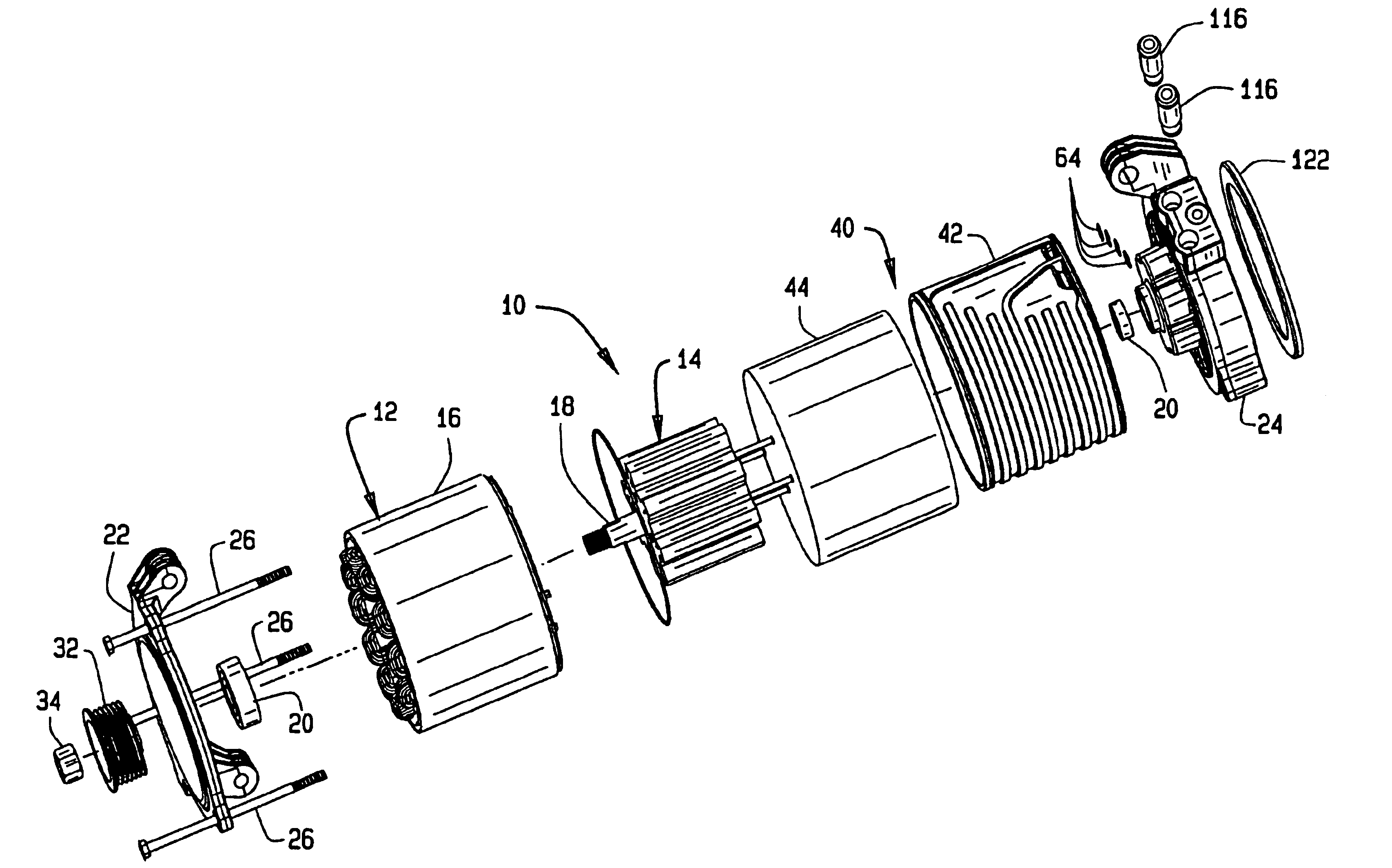
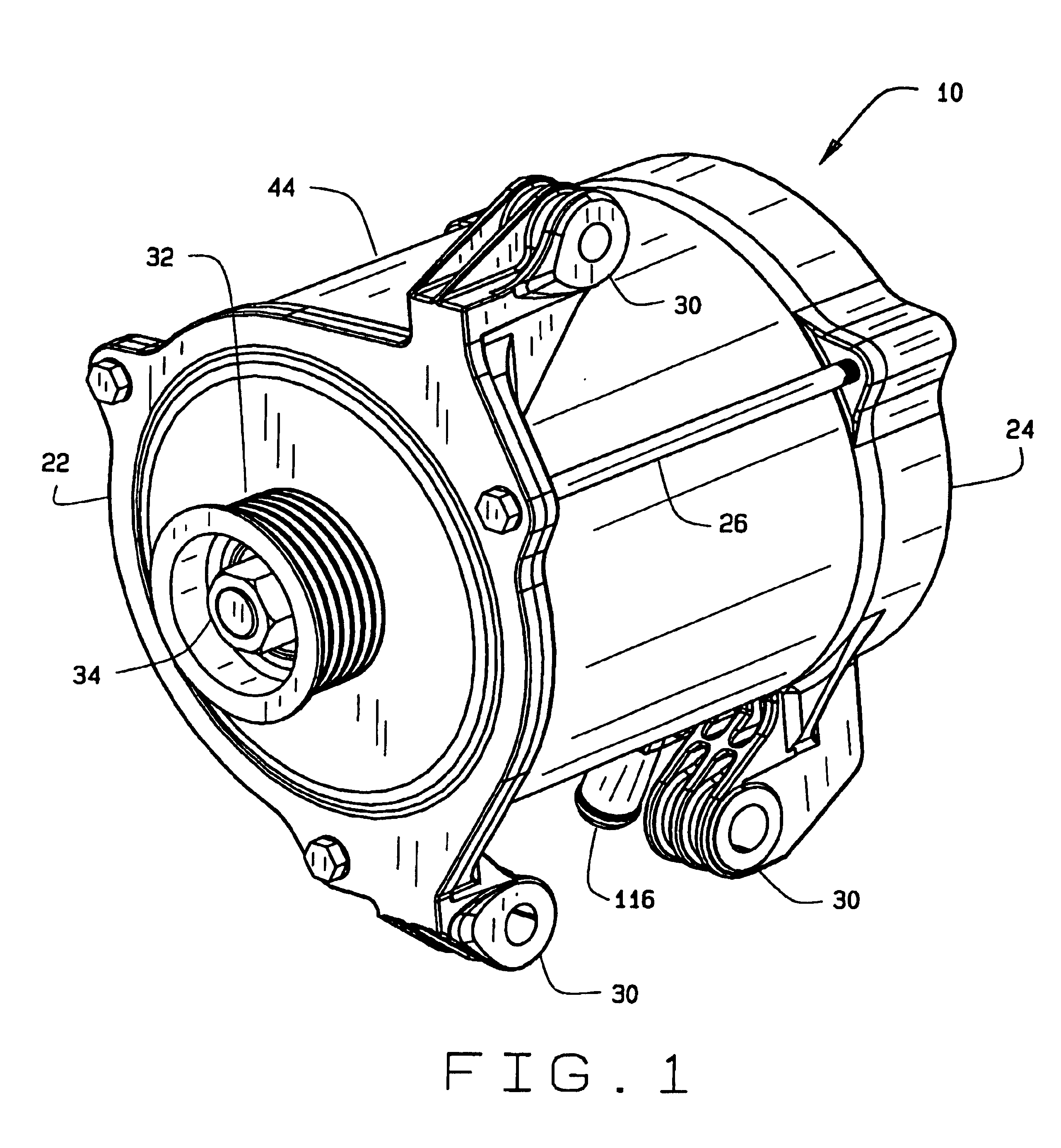
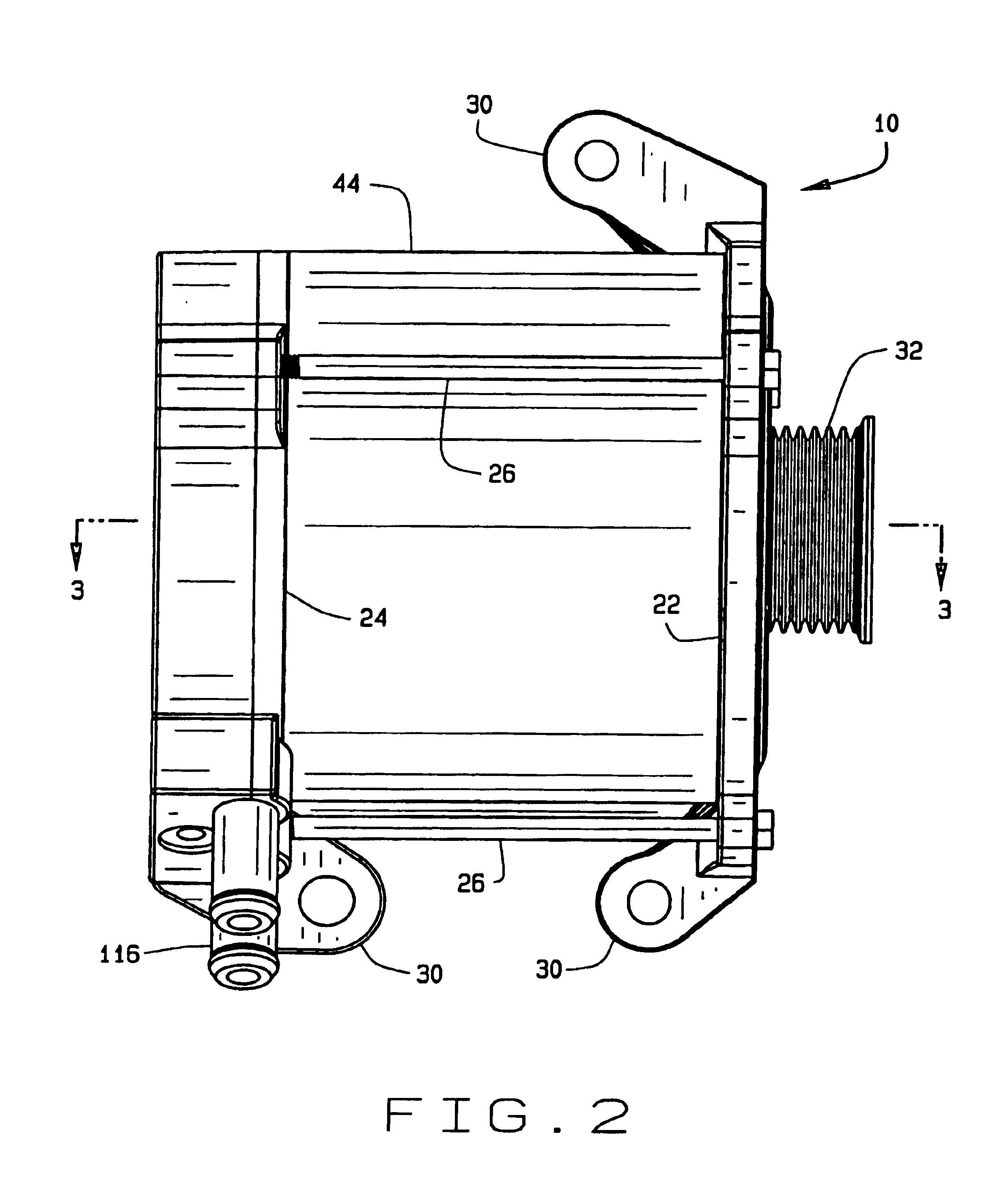
[0020]Referring now to the drawings and in particular to FIGS. 1-4, a dynamoelectric machine having a cooling system according to the present invention is designated in its entirety by the reference numeral 10. In one embodiment, the machine 10 is relatively compact and intended for installation in an engine compartment of an automotive vehicle for use as an integrated starter and generator. Although the description herein is primarily with reference to that embodiment, it is understood the other dynamoelectric machines, such as electric motors or generators of other sizes and for other fields of use, do not depart from the scope of this invention.

[0021]The machine 10 includes a stationary assembly or stator (generally designated 12) and a rotatable assembly or rotor (generally designated 14) magnetically coupled to the stator. As is known in the art, the stator holds one or more wire-wound coils, or windings, on a core. The windings may be encapsulated in a potting material (not sh...


PUM


Abstract

A dynamoelectric machine having a cooling system for removing heat uniformly about the machine. The machine includes a cooling jacket defining a flow path for liquid coolant which extends circumferentially of the machine and which reduces loss of coolant pressure. An endshield of the machine is configured for holding electronic components in arrangement integrated with the machine. The endshield has a flow passage for receiving the coolant to remove heat from the electronic components. The flow passage of the endshield and the flow path of the cooling jacket are serially arranged so that the coolant removes heat sequentially from the electronic components and a stator of the machine.

Description

BACKGROUND OF THE INVENTION[0001]This invention relates generally to systems for cooling dynamoelectric machines, and in particular to a cooling jacket and endshield which direct a flow of fluid for removing heat from an integrated starter generator and associated electronics.[0002]Dynamoelectric machines such as electric motors generate heat during operation which may degrade efficiency or damage component parts, such as windings and bearings. Consequently, a machine is typically cooled during operation by a coolant which is circulated through passages in or around the motor to transport heat energy away from hot parts. Cooling is particularly challenging for a relatively small or compact machine, such as an integrated starter generator for an automotive vehicle. That machine must be packaged so that it occupies only a relatively small space in a vehicle engine compartment (e.g., maximum length and diameter dimensions of about six inches), which limits the amount of space available...

Claims


Application Information

Patent Timeline
IPC IPC(8): H02K5/20H02K11/04
CPCH02K5/20H02K5/203
Inventor BOSTWICK, PETER
Owner NIDEC SR DRIVES
Why Eureka
Try Eureka