Multiple source alignment sensor with improved optics

a sensor and optical technology, applied in the field of control systems, can solve the problems of adding the time required to transport components to the imaging station, and achieve the effects of reducing the degree of divergence, reducing the physical size of the optical train itself, and reducing the part coun

Inactive Publication Date: 2005-06-21
CYBEROPTICS
View PDF39 Cites 5 Cited by
  • Summary
  • Abstract
  • Description
  • Claims
  • Application Information

AI Technical Summary

Benefits of technology

[0007]Features of the present invention provide an optical layout that can accommodate the relatively strict enclosure requirements for compact component alignment sensor. Specifically, aspects of the present invention provide a single optical component that reduces the degree of divergence, and preferably substantially collimates light from the plurality of divergent light sources prior to entering the sensing field. In this regard, part count is kept low and the physical size of the optical train itself is relatively small.

Problems solved by technology

One drawback associated with such systems is the added time required to transport the component to the imaging station; to image the component; and to transport the component from the imaging station to the placement location.

Method used


Image

  • Multiple source alignment sensor with improved optics
  • Multiple source alignment sensor with improved optics
  • Multiple source alignment sensor with improved optics

Examples


Embodiment Construction

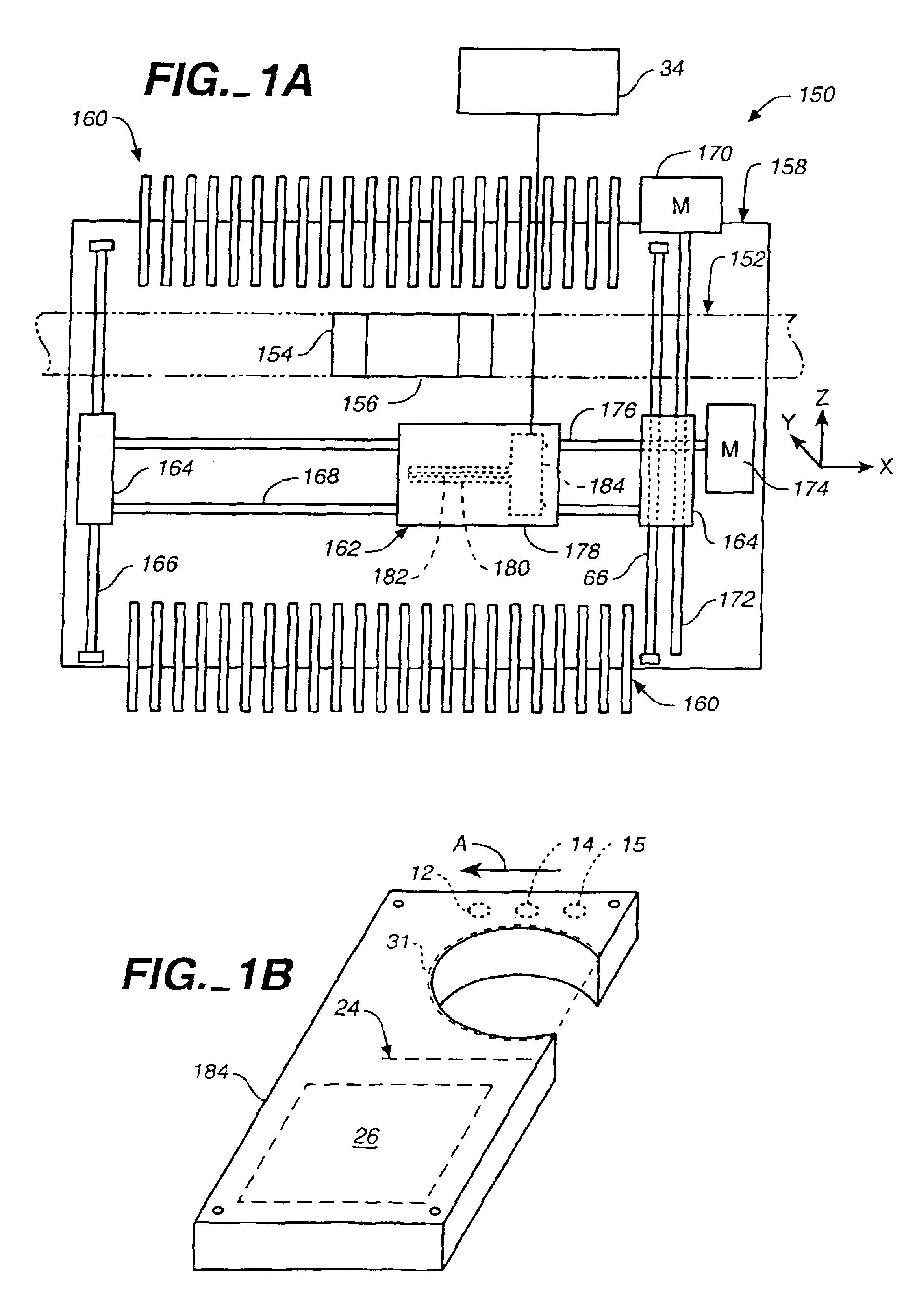
[0019]FIG. 1A is a top plan view of pick and place machine 150 for which embodiments of the present invention are particularly useful. Although the description of FIG. 1A will be provided with respect to pick and place machine 150, other forms of pick and place machines such as split gantry designs, can be used. As illustrated in FIG. 1A, machine 150 includes transport mechanism 152 that is adapted to transport a workpiece such as a printed circuit board. Transport mechanism 152 includes mounting section 154 and conveyor 156. Transport mechanism 152 is disposed on base 158 such that the workpiece is carried to mounting section 154 by conveyor 156. Feeder mechanisms 160 are generally disposed on either side of transport mechanism 152 and supply electronic components thereto. Feeders 160 can be any suitable devices adapted to provide electronic components.

[0020]Pick and place machine 150 includes head 162 disposed above base 158. Head 162 is moveable between either of feeder mechanism...


PUM


Abstract

Features of the present invention provide an optical layout that can accommodate the relatively strict enclosure requirements for compact component alignment sensor. Specifically, aspects of the present invention provide a single optical component that reduces the degree of divergence, and preferably substantially collimates light from the plurality of divergent light sources prior to entering the sensing field. In this regard, part count is kept low and the physical size of the optical train itself is relatively small.

Description

CROSS-REFERENCE TO RELATED APPLICATIONS[0001]This application is a Continuation-In-part Application of U.S. patent application Ser. No. 09 / 767,199 filed Jan. 22, 2001 now U.S. Pat. No. 6,762,847 entitled Laser Align Sensor with Sequencing Light Sources; The application is also a non-provisional application of, and claims priority to, U.S. Provisional Application Ser. No. 60 / 406,822, filed Aug. 29, 2002 and entitled Multiple Source Laser Align Sensor with Improved Optics.BACKGROUND OF THE INVENTION[0002]The present invention relates to control systems which align electrical components for precise placement via pick-and-place machines onto surfaces such as printed circuit boards, hybrid substrates containing circuitry traces, and other carriers of circuit tracings. More specifically, the present invention relates to a non-contact light-based sensor system which precisely determines angular orientation and location (x, y) of components to allow a pick and place machine to correct angul...

Claims


Application Information

Patent Timeline
Patent Type & Authority Patents(United States)
IPC IPC(8): H05K13/04G01B11/03
CPCH05K13/0413H05K13/0813
Inventor MADSEN, DAVID D.KRANZ, DAVID M.CASH, II, FREDERICK M.
Owner CYBEROPTICS
Why Eureka
Try Eureka