Optical fiber enclosure system using integrated optical connector and coupler assembly

a technology of optical fiber and enclosure system, applied in the field of optical fiber communication system, can solve the problems of consuming valuable space in the fiber distribution frame, requiring protective packaging unable to meet the requirements of the coupler cassette,

Inactive Publication Date: 2005-06-21
COMMSCOPE TECH LLC
View PDF36 Cites 185 Cited by
  • Summary
  • Abstract
  • Description
  • Claims
  • Application Information

AI Technical Summary

Benefits of technology

[0014]Preferred embodiments of the present invention are used as optical monitoring devices in an optical network system, as a wavelength division multiplexing assembly, an optical tap and as an optical power splitter. In a preferred embodiment, the integrated connector and coupler assembly is included in an optical transport network system for network monitor

Problems solved by technology

Some of the difficulties associated with optical fibers include concerns related to the bend radius of the fiber cable and coupling.
This optical coupler cassette requires protective packaging and consumes valuable space in the fiber d

Method used


Image

  • Optical fiber enclosure system using integrated optical connector and coupler assembly
  • Optical fiber enclosure system using integrated optical connector and coupler assembly
  • Optical fiber enclosure system using integrated optical connector and coupler assembly

Examples


second embodiment

[0097]Typically, the connectors 122 need to be available for routine cleaning and inspection. Access to the rear connectors is important since the fibers are managed behind the adapters 104. a cassette 100A that provides improved access to the connectors is referred to herein as an open cassette and is shown in FIGS. 17A and 17B. In this embodiment, the fanout devices 120A are mounted in close proximity to the front of the cassette or directly to the front panel 102. The fibers 380 between the fanout devices 120A and the connectors are left floating or are managed minimally while still allowing access and removal from the rear of the cassette.

[0098]The cassette 100A includes adapters 104, adapter plugs 106, fiber optic connectors 122, front face panel 102, mounting plate 10A, panel arm 102A and fanout devices 120A.

[0099]The adapters are mounted to the front face of the cassette. The panel arm 102A extends from the panel and is attached to mounting plate 100A. One or more fanout devi...

first embodiment

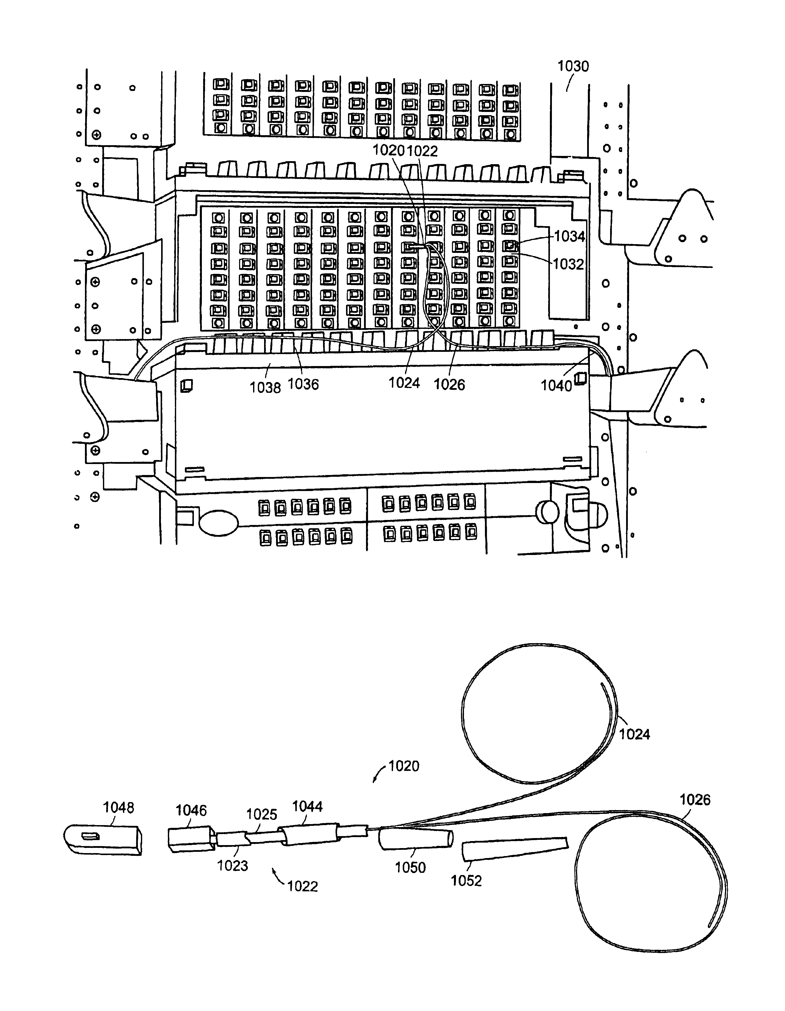
[0116]a removable adapter is shown in FIGS. 37A and 37B. The adapter 600, preferably made of plastic, includes a body 602, connector recesses 604, engagement member 605 and location bosses 612. The engagement member 605 includes a hinge 610, finger tab 606 and engagement tang or tab 608. FIGS. 38A and 38B show the adapter 600 with connector pigtails 620A, 620B mounted to the recesses 604.

[0117]As shown in FIGS. 39A and 39B, the adapter can be mounted to an adapter panel 700. The panel has a cutout 706 that includes a plurality of slots 704 on the right side. The finger tab 606 sits in the slot 704 and the engagement tang snaps into the slot for holding the adapter in place in the panel. The adapter is disengaged by squeezing the finger tab 606 and removing the adapter from the slot.

[0118]A second embodiment of a removable adapter is shown in FIGS. 40A and 40B. The adapter 650, preferably made of plastic, includes a body 652, connector recesses 658, engagement members 655 and locatio...


PUM


Abstract

An optical fiber enclosure system includes a plurality of integrated optical connector and coupler assemblies. The first optic coupler is integrated adjacent to the ferrule in the connector. In a preferred embodiment, the integrated optical connector coupler is constructed in a compact package such that when installed in the optical fiber enclosure no part of the coupler connector assembly protrudes beyond the footprint of the fiber enclosure and yet maintains an industry recommended minimum bend radius of 1.5 inches on the output cable ports thus allowing the fiber enclosure front panel to close without impinging on the cables of the assembly.

Description

BACKGROUND OF THE INVENTION[0001]With the growth of fiber optic communication systems, numerous devices have been developed to house and manage the complex assemblies needed.[0002]One such system is known as an optical fiber cross-connect enclosure. Standard enclosures include a sheet metal housing with removable hinged front and rear doors. For fiber optic patching applications, a removable hinged bulkhead divides the housing into a front and rear compartment with the rear compartment typically being deeper than the front. Removable panels, which contain various numbers of fiber optic adapters, are mounted to the bulkhead. In a typical application, fiber optic jumpers are routed to the front and rear compartments for patching. Front access to the front compartment is provided through ports at the bottom of both sides with routing rings positioned along a front management plate mounted to the bottom of the housing. Bend radius guides are usually mounted to the housing to prevent sha...

Claims


Application Information

Patent Timeline
IPC IPC(8): G02B6/28G02B6/38G02B6/34G02B6/44
CPCG02B6/2804G02B6/4452G02B6/3897G02B6/3825G02B6/3898G02B6/3845G02B6/44715G02B6/44528
Inventor HENSCHEL, JAMES J.COOPER, RONALDNOONAN, MICHAEL
Owner COMMSCOPE TECH LLC
Why Eureka
Try Eureka