Stirling engine

a technology of stirling engine and engine body, which is applied in the field of stirling engine, can solve the problems of limited application of prior art stirling engine to a power source, and the responsiveness of motion control is significantly low, so as to increase the degree of freedom of engine layout and enhance the applicability of the engin

Inactive Publication Date: 2005-06-28
HONDA MOTOR CO LTD
View PDF9 Cites 41 Cited by
  • Summary
  • Abstract
  • Description
  • Claims
  • Application Information

AI Technical Summary

Benefits of technology

[0007]In view of the foregoing, the present invention has been made, and an object of the present invention is to provide a Stirling engine capable of disposing a displacer unit and a power cylinder unit separately from each other, and increasing the degree of freedom of layout of the engine, thereby enhancing the applicability of the engine.

Problems solved by technology

Accordingly, since the motion control of the power piston of the prior art Stirling engine is performed only by adjusting heat generated by a heating portion of a displacer unit, the responsiveness of the motion control is significantly low, and therefore, the application of the prior art Stirling engine is limited to a power source of an apparatus in which a variation in load is relatively small.

Method used


Image

  • Stirling engine
  • Stirling engine
  • Stirling engine

Examples


first embodiment

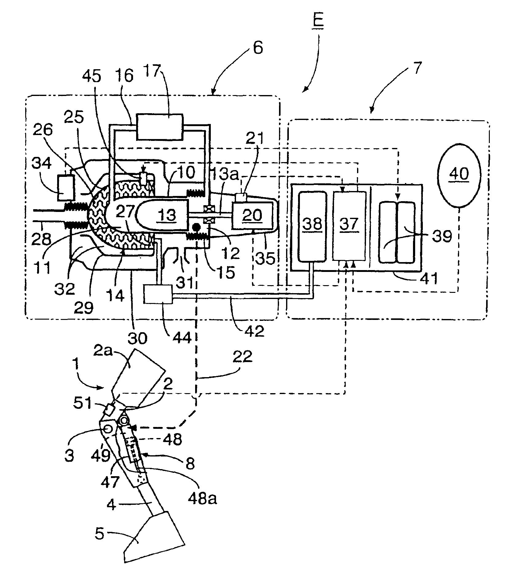
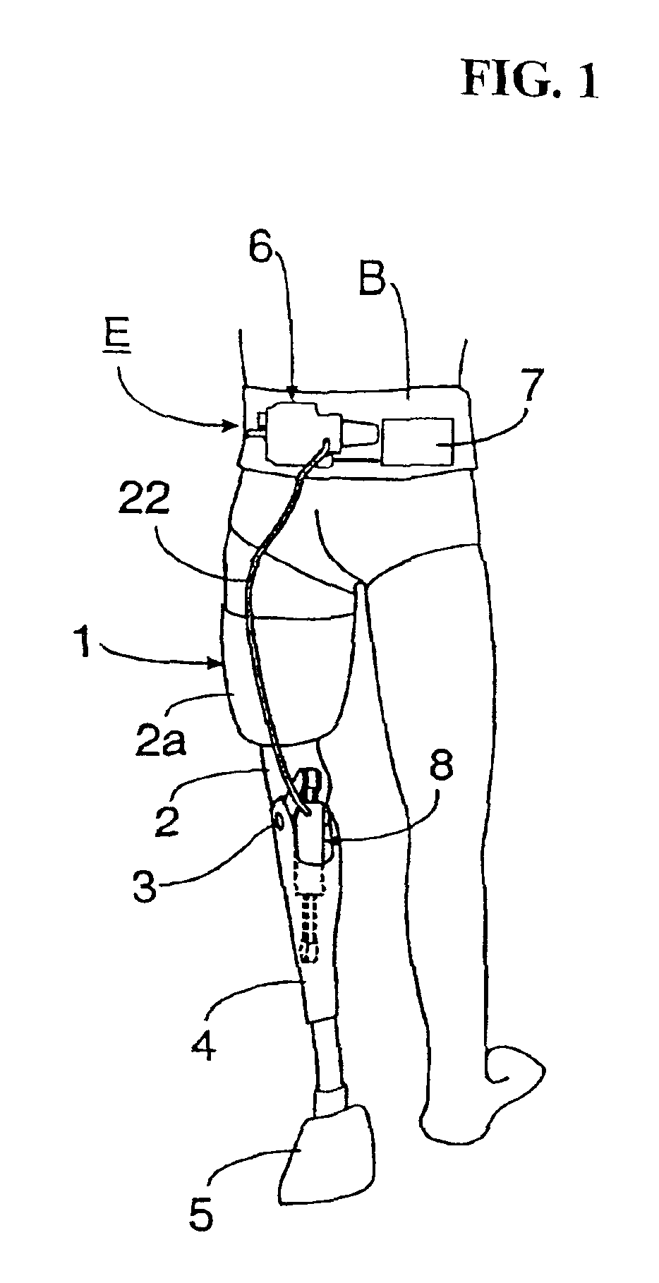
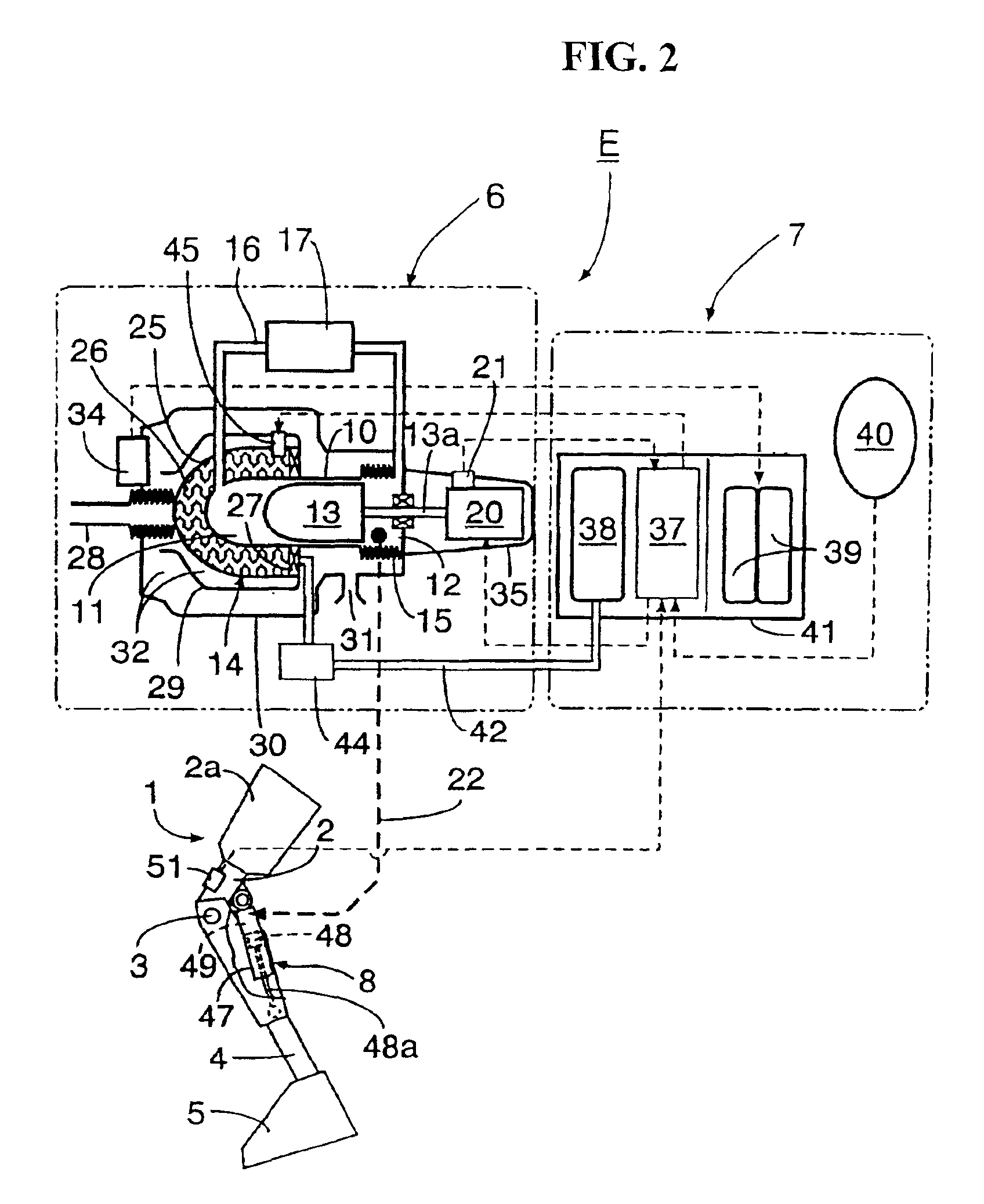
[0039]the present invention shown in FIGS. 1 and 2 will be described below. In FIGS. 1 and 2, a Stirling engine E of the present invention is illustrated which is typically used for driving a prosthetic leg 1. The prosthetic leg 1 includes a thigh portion 2 integrated with a socket 2a in which a user's remaining thigh portion is to be inserted. A shank portion 4 is bendably / stretchably connected to a lower end of the thigh portion 2 via a joint 3. A foot portion 5 is connected to a lower end of the shank portion 4.

[0040]The Stirling engine E includes a displacer unit 6 and a control unit 7, which are mounted on a belt B worn around a user's waist portion. A power cylinder unit 8 is mounted on the prosthetic leg 1 at a position between the thigh portion 2 and the shank portion 4. A pressure conduit 22 is provided for transmitting a pressure generated in the displacer unit 6 to the power cylinder unit 8. A configuration of such a Stirling engine E will be more fully described with ref...

second embodiment

[0068] since the pressure in the compression chamber 12 of the displacer unit 6 is converted into a hydraulic pressure by the hydraulic converter 53, and the hydraulic pressure is transferred to the operation chamber 49 of the power cylinder 47. Thus, it is possible to eliminate the occurrence of elastic compression, which has been caused for a working gas, in the pressure conduit 22 and the operation chamber 49, and hence to improve a pressure transmission efficiency. Further, since the pressure conduit 22 is filled with a non-compressive fluid, it is possible to eliminate a possibility that the inner volume of the pressure conduit 22 becomes a dead volume of the Stirling engine E, and hence to improve a theoretical efficiency of the Stirling engine E.

[0069]A third embodiment shown in FIG. 8 will be described below. In the third embodiment, a Stirling engine E is used for controlling a posture of a seat of a wheelchair W. In the wheelchair W, a seat 76 is connected via an X-type li...

fourth embodiment

[0070]the present invention shown in FIG. 9 will be described below. A power piston 48 of the Stirling engine E drives a power generator 81 via a crank mechanism 80. An output side of the power generator 81 is connected to a load apparatus 83 such as a battery or an electric motor via load adjusting means 82. The load adjusting means 82, which is adapted to adjust a load applied to the load apparatus 83, is controlled by the electronic control unit 37 on the basis of detection signals from a displacer piston sensor 21 and a power piston sensor 51.

[0071]The other configurations are the same as those of the Stirling engine according to the first embodiment, and therefore, parts in FIG. 9 corresponding to those in the Stirling engine E according to the first embodiment are designated by the same reference numerals and the overlapped description thereof is omitted.

[0072]According to the fourth embodiment, even if heat generated by the combustor 14 of the displacer unit 8 is somewhat var...


PUM


Abstract

To provide a Stirling engine and a control unit for a Stirling engine capable of disposing a displacer unit and a power cylinder unit separately from each other, thereby increasing the degree of freedom of layout thereof. A displacer unit and a power cylinder unit of a Stirling engine E are disposed separately from each other. A compression chamber of the displacer unit is connected to an operation chamber of the power cylinder unit via a pressure conduit. A control actuator capable of arbitrarily controlling the displacer piston of the displacer unit is connected to the displacer piston.

Description

CROSS-REFERENCE TO RELATED APPLICATIONS[0001]The present application claims priority under 35 USC 119 to Japanese Patent Application Nos. 2001-071796 filed on Mar. 14, 2001 and 2001-075568 filed on Mar. 16, 2001 the entire contents thereof are hereby incorporated by reference.[0002]1. Field of the Invention[0003]The present invention relates to a Stirling engine and a control system for a Stirling engine including a displacer unit in which a displacer piston is slidably fitted in a displacer cylinder so as to partition the inside of the cylinder into an expansion chamber and a compression chamber. A power cylinder unit is provided in which a power piston is slidably fitted in a power cylinder so as to form an operation chamber in communication with the compression chamber in the cylinder.[0004]2. Description of the Background Art[0005]A Stirling engine is known as disclosed, for example, in a handbook entitled “Car Engineering Series, Vol. 8 ‘Electric Car, New Type Motor’” issued by...

Claims


Application Information

Patent Timeline
Patent Type & Authority Patents(United States)
IPC IPC(8): A61F2/50A61F2/68F02G1/00F02G1/043A61F2/66A61F2/70A61F2/60A61F2/76A61F2/74A61F2/64
CPCA61F2/68F02G1/043A61F2/60A61F2/64A61F2002/6614A61F2002/701A61F2002/704F02G2280/005A61F2002/762A61F2002/7625A61F2002/7655F02G2243/30F02G2244/50A61F2002/747A61F2/70A61F2/74
Inventor ASAI, MASAHIROBAN, MASAKI
Owner HONDA MOTOR CO LTD
Why Eureka
Try Eureka