
Suction connection for dual centrifugal compressor refrigeration systems

a compressor and centrifugal technology, applied in refrigeration components, machines/engines, lighting and heating apparatus, etc., can solve the problems of increased compressor ratio, unstable condition of surge or surge, so as to improve liquid/vapor separation and distribute evenly

Inactive Publication Date: 2005-06-28
JOHNSON CONTROLS TYCO IP HLDG LLP
View PDF20 Cites 9 Cited by
  • Summary
  • Abstract
  • Description
  • Claims
  • Application Information

AI Technical Summary

Benefits of technology

The present invention is about a suction connection for a refrigeration system that helps a surging compressor recover from its instability. The suction connection has a protrusion that disturbs the axial flow of refrigerant vapor in the evaporator, encouraging the refrigerant vapor to flow into the suction connection of the surging compressor. This results in a more equal distribution and improved liquid / vapor separation with the evaporator heat exchanger. The invention can be used in a dual compressor system or a multiple compressor refrigeration system.

Problems solved by technology

During operation, a compressor instability or surge condition can occur in a centrifugal compressor, wherein the compressor cannot pump the flow against its discharge pressure.
Surge or surging is an unstable condition that may occur when compressors, such as centrifugal compressors, are operated at light loads and high pressure ratios.
A lower suction pressure will increase the compressor ratio and decrease the stability of a centrifugal compressor.
Surging, if uncontrolled, can cause excessive vibrations in both the rotating and stationary components of the compressor, and may result in permanent compressor damage.
In the case where the drive device of the compressor is an electric motor, the oscillations in torque and power caused by a surge condition can result in oscillations in motor current and excessive electrical power consumption.
In dual compressor applications, the occurrence of a surge or lack of pumping condition on one compressor results in the other compressor having an increase in refrigerant flow.
This increase in refrigerant flow to the non-surging compressor makes it more difficult for the surging compressor to recover from its instability.
Axial gas flow within the evaporator to the stable compressor will pass over a suction opening of the unstable compressor, thereby lowering the pressure at the unstable compressor suction connection which further contributes to instability.
Both of these solutions have several drawbacks including a more complicated and expensive implementation of the evaporator.
A completely separated evaporator shell would result in less heat exchanger surface being available during single compressor operation, and therefore would provide less effective heat transfer and reduced performance.
This provides less effective vapor separation than if the entire baffle or mesh pad section were utilized.

Method used


Image

  • Suction connection for dual centrifugal compressor refrigeration systems
  • Suction connection for dual centrifugal compressor refrigeration systems
  • Suction connection for dual centrifugal compressor refrigeration systems

Examples


Embodiment Construction

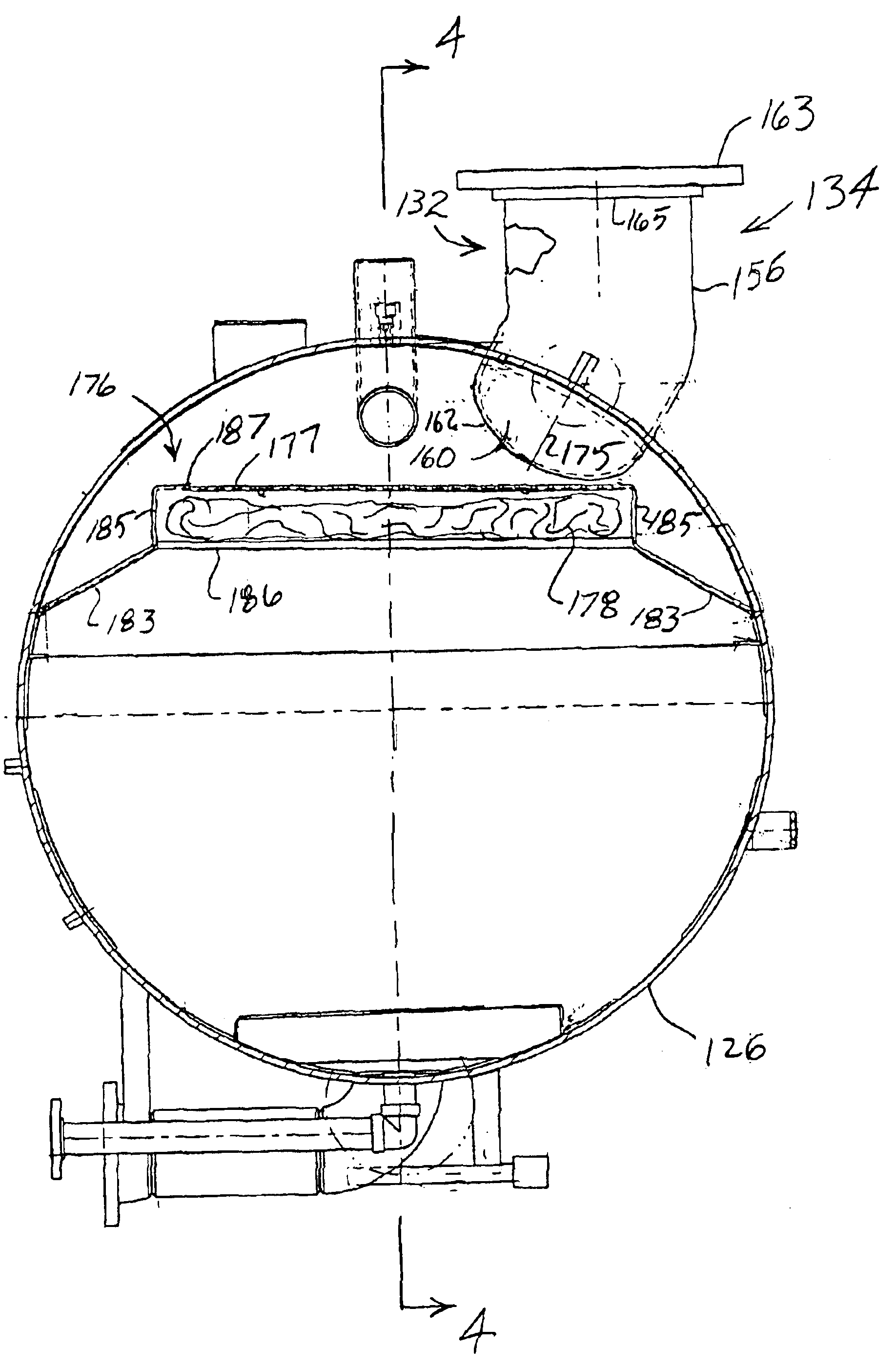
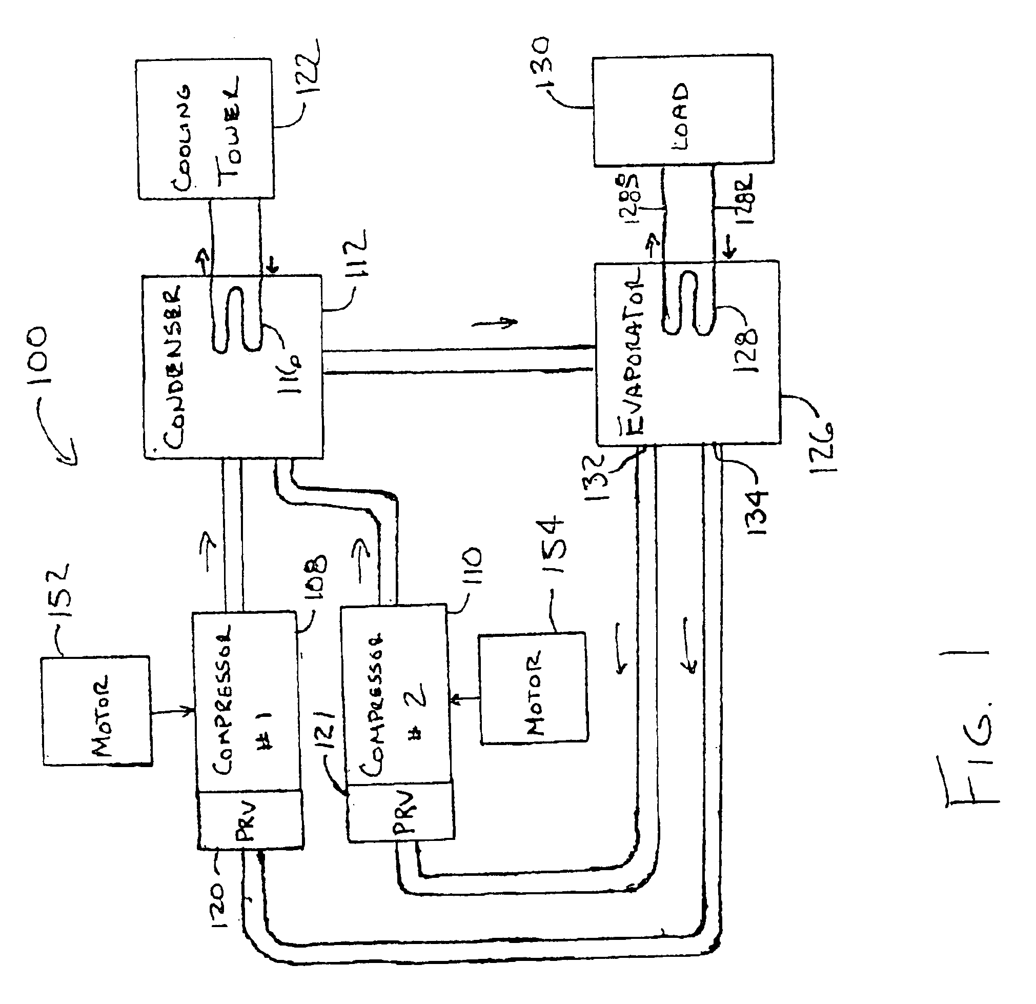
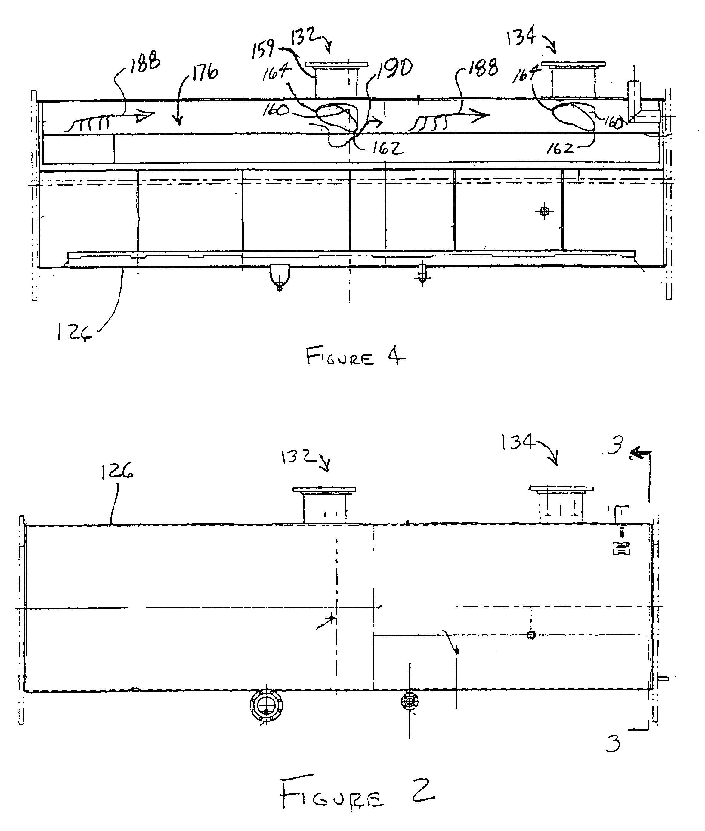
[0020]A general dual compressor system to which the invention can be applied is illustrated, by means of example, in FIG. 1. As shown, the HVAC, refrigeration or liquid chiller system 100 includes a first compressor 108, a second compressor 110, a condenser 112, a water chiller or evaporator 126, and a control panel (not shown). In another embodiment of the present invention, the liquid chiller system 100 could use one compressor or three or more compressors connected in parallel similar to the connection of the first and second compressors 108, 110. The control panel receives input signals from the system 100 that indicate the performance of the system 100 and transmits signals to components of the system 100 to control the operation of the system 100. The conventional liquid chiller system 100 includes many other features which are not shown in FIG. 1. These features have been purposely omitted to simplify the drawing for ease of illustration.

[0021]The compressors 108 and 110 comp...


PUM


Abstract

A dual centrifugal compressor refrigeration system has one evaporator for both compressors. The evaporator provides the centrifugal compressors with refrigerant vapor through separate suction connections for each compressor. Each suction connection has a protrusion that extends into the evaporator vessel to disturb the axial flow of refrigerant vapor in the evaporator vessel. The disturbance of the axial flow of refrigerant vapor in the evaporator vessel permits a surging compressor to draw refrigerant vapor in order to recover from the surge condition.

Description

CROSS-REFERENCE TO RELATED APPLICATIONS[0001]This application claims the benefit of U.S. Provisional Application No. 60 / 401,354 filed Aug. 6, 2002.BACKGROUND OF THE INVENTION[0002]The present invention relates generally to a suction connection for a compressor. Specifically, the present invention relates to a suction connection in the evaporator that increases the aerodynamic stability of multiple centrifugal compressors operating in parallel in a refrigeration system.[0003]To obtain increased capacity in a refrigeration system, two centrifugal compressors can be connected in parallel to a common refrigerant circuit. Frequently, for capacity control, one of the compressors is designated as a “lead” compressor and the other compressor is designated as a “lag” compressor. The capacity of the refrigeration system, and of each compressor, can be controlled by the use of adjustable pre-rotation vanes or inlet guide vanes incorporated in or adjacent to the suction inlet of each compressor...

Claims


Application Information

Patent Timeline
Patent Type & Authority Patents(United States)
IPC IPC(8): F04D27/02F25B41/00F25B1/053F25B1/04F25B39/02
CPCF04D27/0253F25B41/003F25B1/053F25B39/02F25B2500/01F25B2339/0242F25B2400/075F25B41/40
Inventor BODELL, II, MARK ROBINSONDEITZ, JR., DENNIS L.THOMPSON, RUSSELL MARK
Owner JOHNSON CONTROLS TYCO IP HLDG LLP
Learn More