
Pressure monitoring technique and applications involving wells

Inactive Publication Date: 2005-06-28
BUTLER THOMAS L +1
View PDF4 Cites 8 Cited by
  • Summary
  • Abstract
  • Description
  • Claims
  • Application Information

AI Technical Summary

Benefits of technology

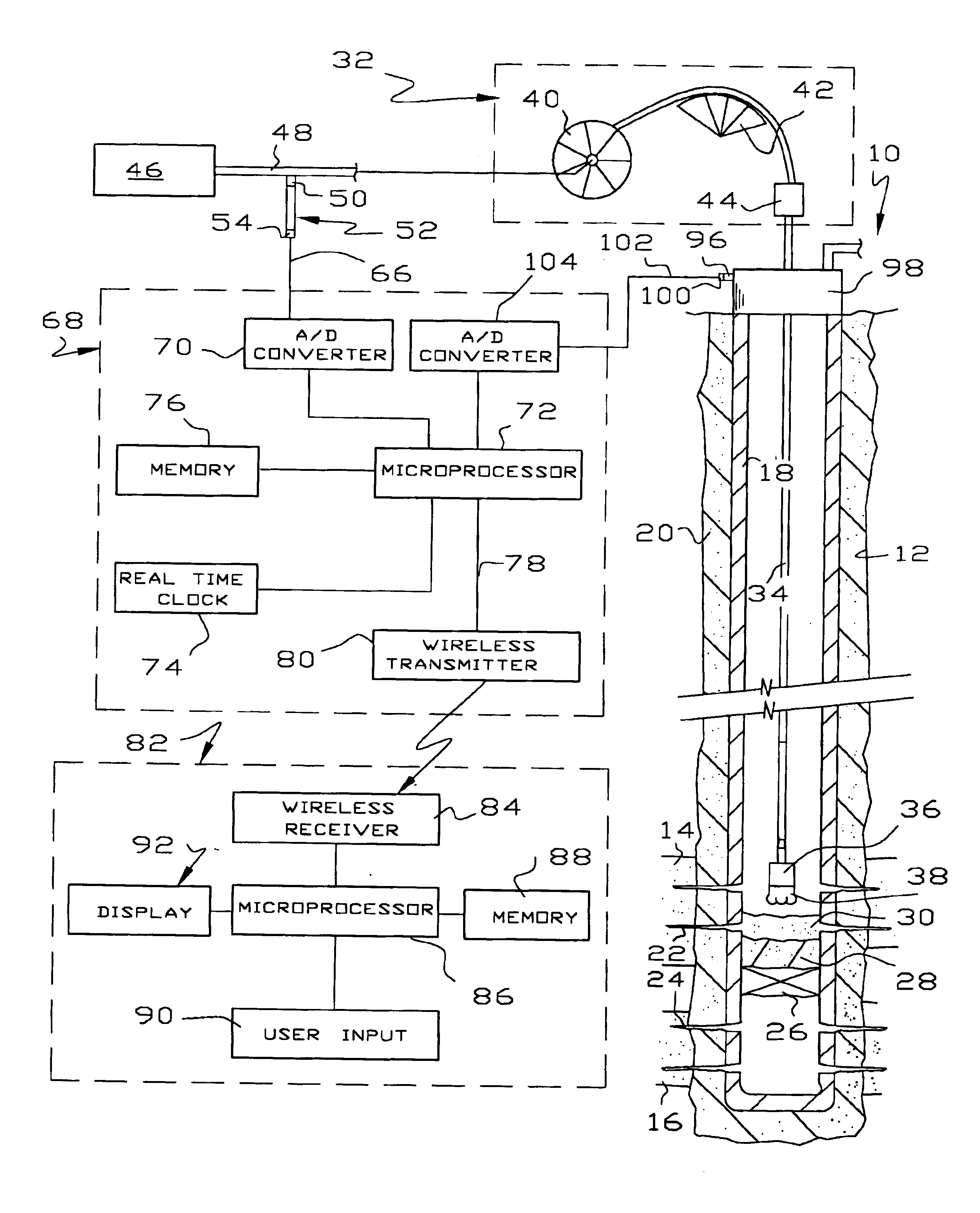
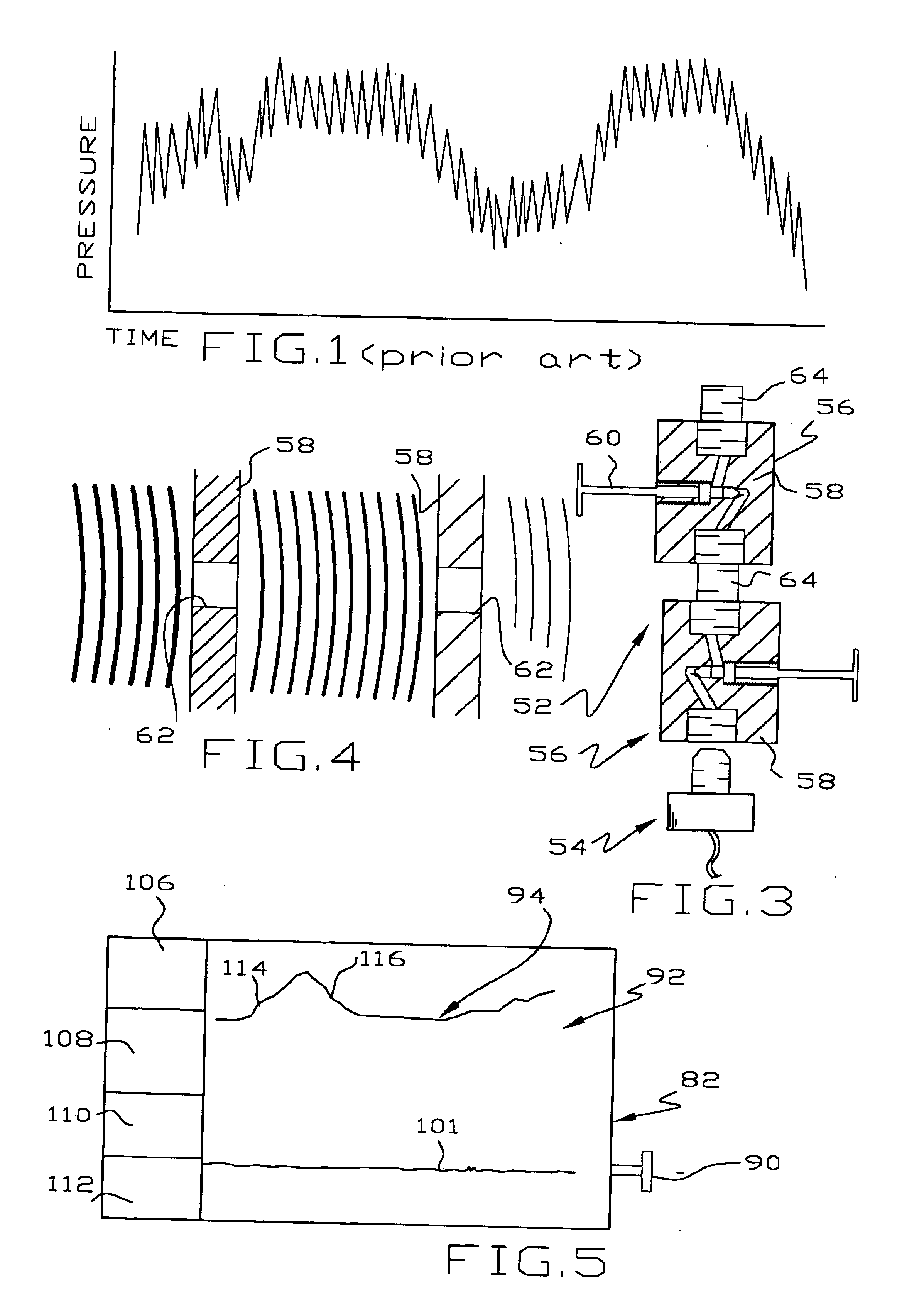
[0007]In another aspect of this invention, a particularly effective and inexpensive damper is described, comprising a pair of needle valves in series. It is not clear exactly why a pair of needle valves are so effective in damping pressure fluctuations. Although not wishing to be bound by any theory of operation, a theory will be advanced hereinafter. Because the needle valves are adjustable, the size and shape of openings are adjustable. It is clear that opening the needle valves completely reduces their damping effectiveness.

Problems solved by technology

It is clear that opening the needle valves completely reduces their damping effectiveness.
Stalling a turbine type liquid driven motor is never desirable for a variety of reasons, including wear on resilient parts on the inside of the motor or, as described more fully below, the fatigue on a coiled tubing work string.

Method used


Image

  • Pressure monitoring technique and applications involving wells
  • Pressure monitoring technique and applications involving wells
  • Pressure monitoring technique and applications involving wells

Examples


Embodiment Construction

[0020]The discharge pressure of high pressure multiplex pumps used to power or manipulate downhole tools in hydrocarbon wells fluctuates so widely and so rapidly that pertinent pressure changes are often masked by, or are smaller than, the fluctuations. This is illustrated in FIG. 1 which is a graph of time versus pressure taken downstream of a conventional pressure snubber that is supposed to damp pressure fluctuations. Every pump acts slightly differently and the fluctuations vary with the operating speed of the pump and other factors. Basically, however, every time the discharge valve of a high pressure multiplex pump opens, a surge of high pressure liquid leaves the pump producing an upward pressure spike. Because most liquids range from mainly incompressible to slightly incompressible, the pressure surges dissipate as the liquid moves down the flow line into which it is discharged. This causes a reduction in pressure at the pump outlet until the next discharge valve opens.

[0021...


PUM


Abstract

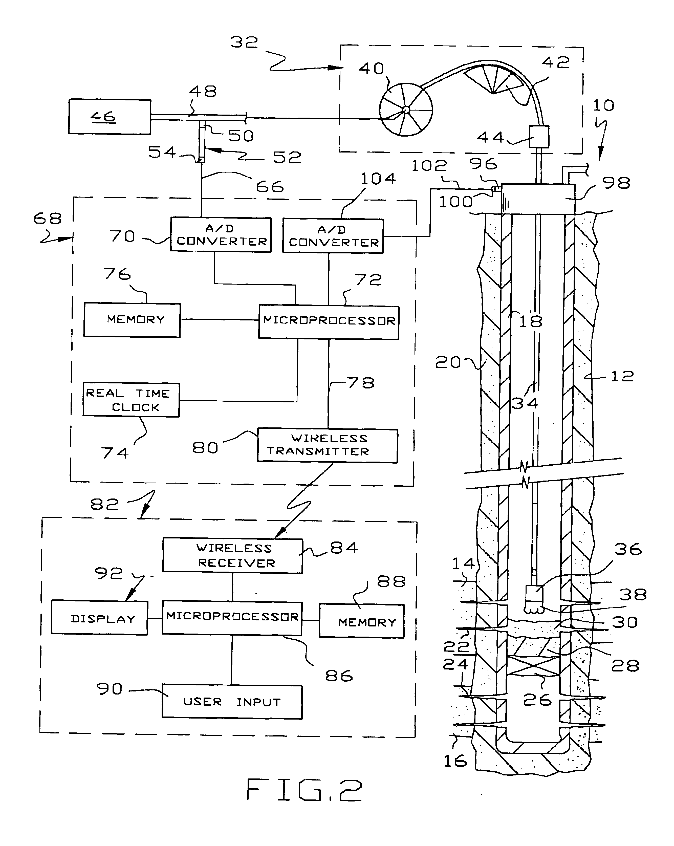
The outlet pressure of a pump that fluctuates rapidly, as is typical of high pressure multiplex pumps, is sensed in a pressure line leading from the main flow line to a damping mechanism. The damping mechanism comprises a pair of small spaced openings, which are preferably adjustable in size. The damping mechanism is ideally a pair of needle valves placed in series so the pressure downstream of the second needle valve fluctuates considerably less than upstream of the first needle valve. The damped pressure is sensed to provide an input to real time graphs showing various pertinent pressure measurements involving the application of pressure, e.g. to monitor downhole tools in hydrocarbon wells. The downhole tools may be fluid driven motors, whipstocks, packers, wiper plugs and the like. In the case of fluid driven or mud motors, a base line pressure taken when the motor is idling is compared to the pressure when the motor is drilling to detect the onset of motor stall.

Description

[0001]This invention relates to a method and apparatus for monitoring pressure and, more particularly, to applications of pressure monitoring in hydrocarbon wells.BACKGROUND OF THE INVENTION[0002]The equipment used in drilling, completion and working over of hydrocarbon wells in the past has almost entirely been a matter of brute force rather than finesse. Drilling rigs in particular and workover rigs to a lesser extent are characterized by massive machinery, high horsepower pumps and a brute force approach to problems. In contrast, coiled or spooled tubing units are much more finesse oriented because the pipe that comprises the work string is much smaller, much thinner and much less capable of accommodating large forces. At one time, coiled tubing units were widely known as an invitation to a fishing job because there were so many mechanical failures of the work string or the loss of bottom hole components in wells.[0003]It is a tribute to the manufacturers of coiled tubing and coi...

Claims


Application Information

Patent Timeline
IPC IPC(8): E21B47/06
CPCE21B47/06
Inventor BUTLER, THOMAS L.BUTLER, T. GLEN
Owner BUTLER THOMAS L
Learn More