General purpose bombs

a general purpose and bomb technology, applied in the field of general purpose bombs, can solve the problem of natural prejudice against such an approach to be unfounded

Inactive Publication Date: 2005-06-28
BAE SYSTEMS PLC
View PDF19 Cites 13 Cited by
  • Summary
  • Abstract
  • Description
  • Claims
  • Application Information

AI Technical Summary

Benefits of technology

[0022]It can be advantageous to provide a liner which progressively increases in thickness from its periphery towards its center, so that for example the thickness at the center is between 1.5 and 2.5 times the minimum thickness at or near the periphery.

Problems solved by technology

The Applicant has, however, generated a new concept and undertaken expensive trials which, against reasonable expectation, have demonstrated the natural prejudice against such an approach to be unfounded.

Method used


Image

  • General purpose bombs
  • General purpose bombs

Examples


Embodiment Construction

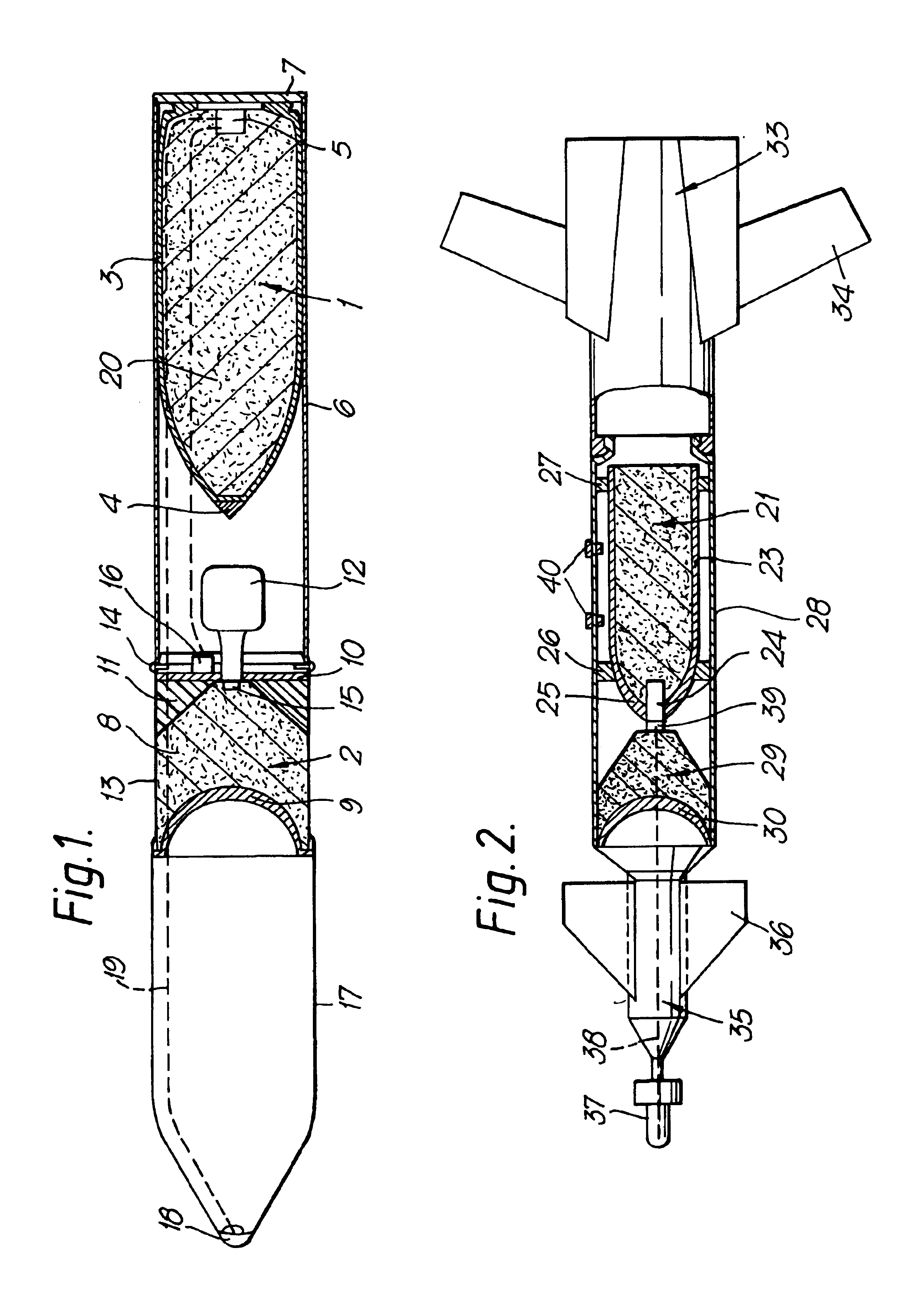
[0027]As shown in FIG. 1, a munition in accordance with the present invention comprises a 1000 lb general purpose bomb 1 and a penetrator warhead 2 in the form of a hollow charge.

[0028]The general purpose bomb 1 comprises a fragmenting steel case 3 having a hardened nose portion 4 and a filling of high explosive such as Torpex. In the base of the bomb there is provided a suitable fuze 5. The steel case 3 has an outer diameter of approximately 16½ inches, and the bomb if as nominal all-up weight of 1000 lb. The bomb may be carried within a relatively light steel outer case 6 having an end closure plate 7 and an access opening 12 closed by a removable cover.

[0029]A tail unit (not shown) can be attached at the rear of the end plate 6, for giving stability and desired flight characteristics to the munition in flight.

[0030]The penetrator warhead 2 comprises a cylindrical body of high explosive 8 such as 60 / 40 RDX / TNT mixture. The forward face of the explosive charge 8 is concave, and is ...


PUM


Abstract

A general purpose bomb having a shaped charge penetrator warhead mounted in the front of the bomb and facing forward, in which the caliber of the warhead is at least 90% of the caliber of the general purpose bomb.

Description

BACKGROUND OF THE INVENTION[0001]1. Field of the Invention[0002]This invention relates to general purpose bombs. The general purpose bomb can be used to great effect against a variety of targets, depending upon its capabilities, and the nature of the target.[0003]2. Discussion of the Prior Art[0004]A principal use is against hard targets such as hardened aircraft shelters, bridge piers, aircraft runways, and the like. Against such hard targets the general purpose bomb is generally ineffective unless the bomb is able to penetrate into the target prior to detonation, so that the blast and heave effects on the target are maximised.[0005]However, in modern warfare certain targets are extremely well protected. Hardened aircraft shelters may be protected by one or more meters of reinforced concrete which may be covered by a layer of soil or sand. Aircraft runways may be several meters thick. Tactical bunkers may be protected by several meters of reinforced concrete with mounded earth prov...

Claims


Application Information

Patent Timeline
Patent Type & Authority Patents(United States)
IPC IPC(8): F42B12/02F42B12/16F42B25/00
CPCF42B12/16
Inventor GETHINGS, BERNARD C.FLYNN, DENNIS J.APPLETON, JOHN A.
Owner BAE SYSTEMS PLC
Why Eureka
Try Eureka