Double-ended blower and volutes therefor

a double-ended blower and volutating technology, which is applied in the direction of wind motors with parallel air flow, wind motors with perpendicular air flow, liquid fuel engine components, etc., can solve the problems of patient inability to receive adequate treatment, impeller acceleration and deceleration, excessive stress on impeller, motor and bearings, etc., to achieve less acoustic noise, improve reliability, and accelerate pressure rise time

Inactive Publication Date: 2005-06-28
RESMED LTD
View PDF14 Cites 218 Cited by
  • Summary
  • Abstract
  • Description
  • Claims
  • Application Information

AI Technical Summary

Benefits of technology

[0008]The present invention, in one aspect, relates to variable speed blowers providing faster pressure rise time with increased reliability and less acoustic noise. Blowers according to the present invention comprise a gas flow path between a gas inlet and a gas outlet, a motor, and an impeller assembly.

Problems solved by technology

A first disadvantage is that in order to switch rapidly between IPAP and EPAP, the impeller must be accelerated and decelerated rapidly.
This causes excessive stress on the impeller, motor, and bearings.
However, if the impeller is accelerated slowly, the pressure rise may be unsatisfactorily slow, and thus, the patient may not receive adequate treatment.
Rapid acceleration and deceleration of the motor and impeller also result in excessive heat generation and undesirable acoustic noise.
In addition, design engineers are often forced to make a compromise, sacrificing optimal pressure and flow characteristics in favor of achieving a desired peak pressure.

Method used


Image

  • Double-ended blower and volutes therefor
  • Double-ended blower and volutes therefor
  • Double-ended blower and volutes therefor

Examples


Embodiment Construction

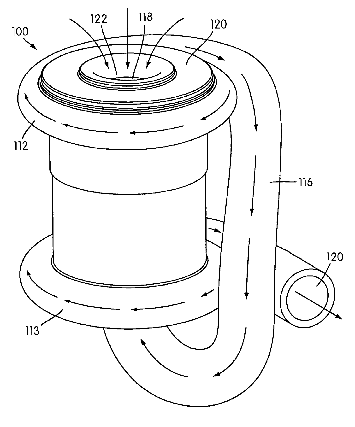
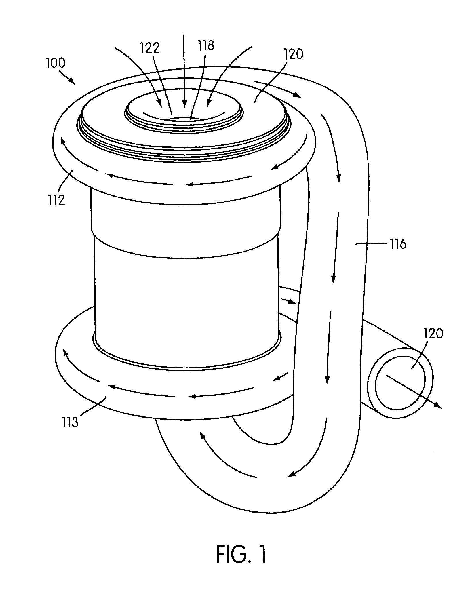
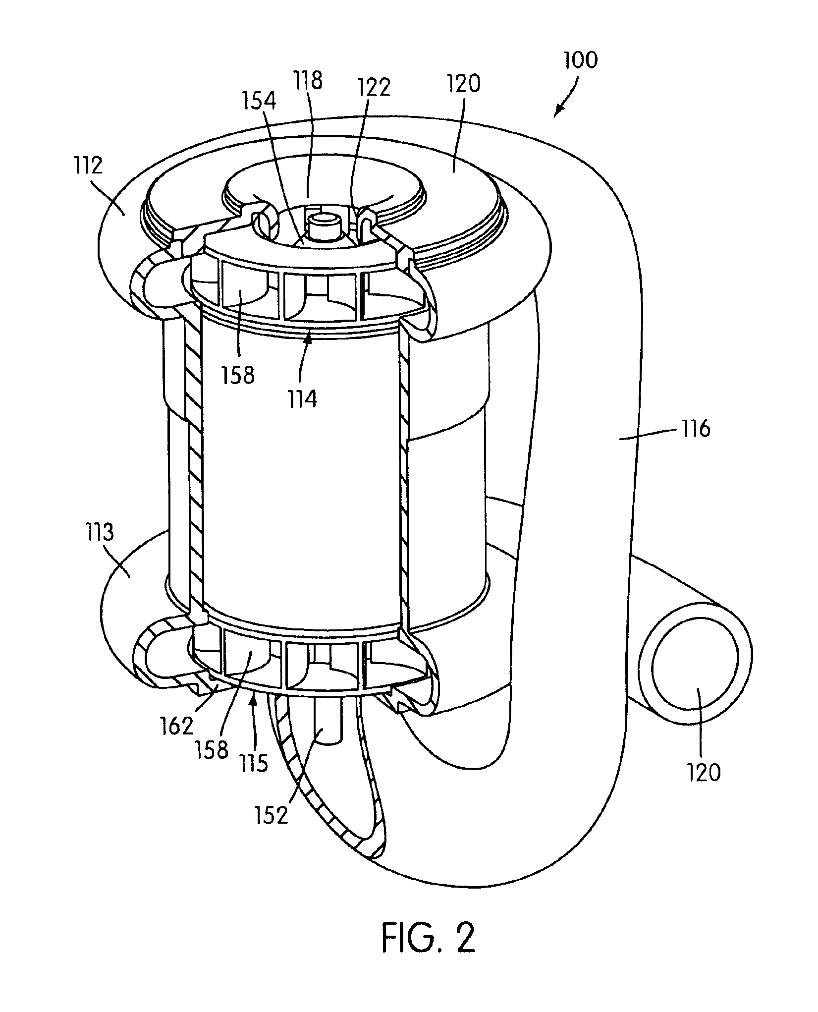
[0025]Referring now to the Figures, FIG. 1 is a perspective view of a double ended blower 100 according to a first embodiment of the present invention. Blower 100 has a generally cylindrical shape with impeller housings, or volutes 112, 113, disposed at each end. Thus, blower 100 accommodates two impellers 114, 115, which are best seen in the cut-away perspective view of FIG. 2.

[0026]Referring to FIGS. 1 and 2, the two impellers 114, 115 are placed in fluid communication with one another by an airpath 116. The airpath 116 of blower 100 is comprised of piping that extends from the first volute 112 to the second volute 113, the terminal ends of the airpath 116 being contoured around, and gradually fusing with, the body of blower 100 proximate to the volutes 112, 113 to form a single, integral structure. The airpath 116 may be comprised of rigid piping that is integrally molded with the other components of the blower 100, or it may be comprised of flexible piping (e.g., metallic or pla...


PUM


Abstract

A double-ended variable speed blower for Continuous Positive Airway Pressure (CPAP) ventilation of patients includes two impellers in the gas flow path that cooperatively pressurize gas to desired pressure and flow characteristics. Thus, the double-ended blower can provide faster pressure response and desired flow characteristics over a narrower range of motor speeds, resulting in greater reliability and less acoustic noise.

Description

FIELD OF THE INVENTION[0001]The present invention relates to an apparatus for supplying breathable gas to a human, used in, for example, Continuous Positive Airway Pressure (CPAP) treatment of Obstructive Sleep Apnea (OSA), other respiratory diseases and disorders such as emphysema, or the application of assisted ventilation.DESCRIPTION OF RELATED ART[0002]CPAP treatment of OSA, a form of Noninvasive Positive Pressure Ventilation (NIPPV), involves the delivery of a pressurized breathable gas, usually air, to a patient's airways using a conduit and mask. Gas pressures employed for CPAP can range from 4 cm H2O to 28 cm H2O, at flow rates of up to 180 L / min (measured at the mask), depending on patient requirements. The pressurized gas acts as a pneumatic splint for the patient's airway, preventing airway collapse, especially during the inspiratory phase of respiration.[0003]Typically, the pressure at which a patient is ventilated during CPAP is varied according to the phase of the pati...

Claims


Application Information

Patent Timeline
Patent Type & Authority Patents(United States)
IPC IPC(8): F04D25/16A61M16/00F04D17/00F04D17/12F04D25/00
CPCA61M16/0057F04D17/12F04D17/122A61M16/0069F04D27/004F04D29/582F04D25/166A61M16/0816A61M16/0875F04D17/164Y02B30/70F04D1/00
Inventor DALY, GEOFFREY D.VIRR, ALEXANDERLEA, STEPHEN A.MARTIN, DION CHARLES C.REED, NICHOLAS JPUCKERIDGE, LARRYFU, TIMOTHY TSUN-FAI
Owner RESMED LTD
Why Eureka
Try Eureka