Laser guidance system

a laser guidance and laser technology, applied in the direction of distance measurement, instruments, using reradiation, etc., can solve the problems of difficult control, risk of misalignment, collision and damage to the spacecraft, impractical or impossible for a pilot to manually maneuver the spacecraft for docking or berthing,

Inactive Publication Date: 2005-06-28
THE BOEING CO
View PDF5 Cites 13 Cited by
  • Summary
  • Abstract
  • Description
  • Claims
  • Application Information

AI Technical Summary

Benefits of technology

[0009]Advantages of the present invention are that it is lightweight and it provides range and alignment data, thereby allowing a docking spacecraft to fly a target-centered approach trajectory to a docking target vehicle without requiring any power or control from the target vehicle. It also reduces need for high resolution video cameras and image processing for range and attitude estimation during terminal guidance once the docking spacecraft enters the outer boundary of the approach corridor and is aligned with the approach trajectory.

Problems solved by technology

Inertial propulsion systems tend to be difficult to control and present a risk of misalignment and possible collision and damage to the spacecraft.
A difficulty encountered with manual systems is that it is often impractical or impossible for a pilot to manually maneuver a spacecraft for docking or berthing.
For example, some space missions are tenuous and may endanger the pilot, while other space missions include unmanned spacecraft.
Docking based on visible light image data requires advantageous lighting, and it is difficult for cameras to provide adequate image detail for attitude and range estimation.
The disadvantages associated with current docking systems have made it apparent that a new docking system is needed.

Method used


Image

  • Laser guidance system
  • Laser guidance system
  • Laser guidance system

Examples


Embodiment Construction

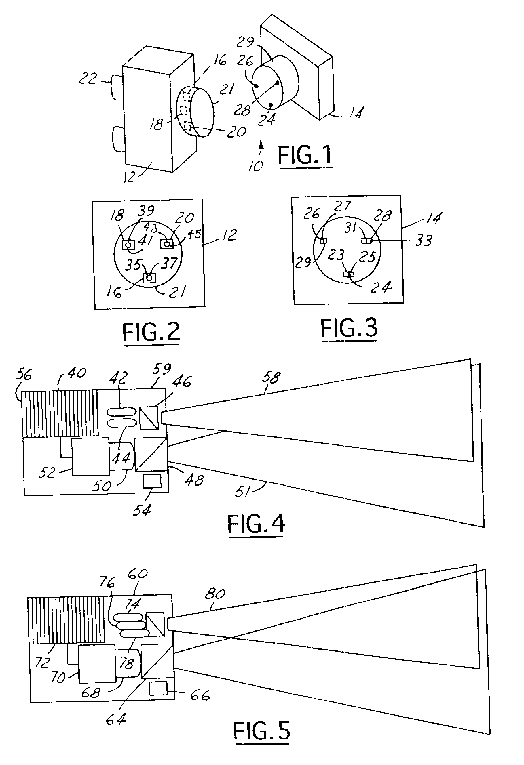
[0022]The present invention is illustrated with respect to a docking system particularly suited to the aerospace field. The present invention is, however, applicable to various other uses that may require docking or vehicle interaction, as will be understood by one skilled in the art.

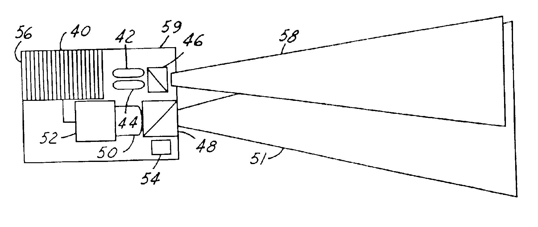
[0023]Referring to FIGS. 1, 2 and 3, a docking system 10, including a target spacecraft 14 (first vehicle) and a chaser spacecraft 12 (second vehicle), is illustrated. The target 14 includes three passive guidance system alignment target reflector system / docking fixtures or reflector systems (first 24, second 26, and third 28) coupled to a docking interface 29. The chaser 12 includes three guidance systems (first 16, second 18, and third 20) coupled to a docking clamp 21, which will be discussed later in detail. The chaser 12 also includes inertial propulsion systems or attitude control devices 22, such as thrusters, control moment gyros, torque rods, etc.

[0024]The guidance systems 16, 18, 20 (also refe...


PUM


Abstract

A guidance system includes a first laser device coupled to a mount, the first laser device adapted to generate a first laser signal having a first wavelength. A second laser device is also coupled to the mount and directed substantially parallel with the first laser device. The second laser device is adapted to generate a second laser signal having a second wavelength. A first photodiode is adapted to detect the first laser signal, retro-reflected from a first wavelength matched section of a reflector system, and the second laser, signal retro-reflected from a second wavelength matched section of the reflector system. The first photodiode is adapted to generate a first photodiode signal therefrom.

Description

TECHNICAL FIELD[0001]The present invention relates generally to docking vehicles, and more particularly, to a laser guidance system for spacecraft docking.BACKGROUND ART[0002]Spacecraft proximity maneuvering, rendezvous, and docking procedures arise in most space missions, including those with commercial satellites, cargo transfer spacecraft, lunar mission spacecraft and various repair and service spacecrafts. It is well known that conventional spacecraft docking mechanisms include precise control of inertial propulsion systems, such as thrusters, to position an active craft (chaser) in motion relative to a passive craft (target) for docking. Inertial propulsion systems tend to be difficult to control and present a risk of misalignment and possible collision and damage to the spacecraft. Two current approaches to resolve this include manual docking and autonomous docking.[0003]Typical manual docking systems include a video sensor or camera, which generates a visual output for use by...

Claims


Application Information

Patent Timeline
Patent Type & Authority Patents(United States)
IPC IPC(8): B64G1/66B64G1/64G01C3/08F41G7/00
CPCB64G1/646G01S17/74G01S17/48G01S17/42B64G1/1078
Inventor LECROY, JR., JERRY EDWARD
Owner THE BOEING CO
Why Eureka
Try Eureka