Apparatus and method for handling linerless label tape

a linerless label and tape supply technology, applied in the field of linerless label tape system, can solve the problems of increasing the cost of liner material, and reducing the available length of label tape for a given tape supply roll diameter, so as to achieve the effect of minimizing adhesion

Inactive Publication Date: 2005-06-28
3M INNOVATIVE PROPERTIES CO
View PDF217 Cites 19 Cited by
  • Summary
  • Abstract
  • Description
  • Claims
  • Application Information

AI Technical Summary

Benefits of technology

[0016]In one preferred embodiment of the above apparatus, the adhesive side carries an adhesive, where the driven roller includes a contact surface for engaging the linerless tape, and where the contact surface is configured to minimize adhesion with the adhesive side. In one aspect of this embodiment, the contact surface includes a knurled surface for minimizing a surface area of the contact surface.
[0020]In another preferred embodiment of the above apparatus, the driven roller is rotated at a surface speed greater than or equal to that of the driven platter roller. In another preferred embodiment of the above apparatus, the adhesive side carries an adhesive, where the driven roller includes a contact surface for engaging the linerless tape, and where the contact surface is configured to minimize adhesion with the adhesive side. In another aspect of this embodiment, the contact surface includes a knurled surface for minimizing a surface area of the contact surface.
[0023]In a preferred embodiment of the above method, the method includes providing a continuous web of linerless tape includes providing a web of linerless tape having a thickness of less than about 90 microns. In another preferred embodiment of the above method, the method includes providing a web of linerless tape includes providing a web of linerless tape carrying an adhesive on the adhesive side. In yet another preferred embodiment of the above method, the method includes extending the web of linerless tape along a tape path includes establishing a wrap angle of linerless tape around the driven roller between 10°-180°. In another preferred embodiment of the above method, the printing device is a thermal transfer printer and further includes a continuous ribbon disposed between the print head and the print side of the web of linerless tape. In another preferred embodiment of the above method, the method includes, the adhesive side carries an adhesive, and where the driven roller includes a contact surface for engaging the linerless tape, the contact surface being configured to minimize adhesion with the adhesive side. In another preferred embodiment of the above method, the contact surface includes a knurled surface for minimizing the surface area of the contact surface.
[0026]In another preferred embodiment of the above method, the adhesive side carries an adhesive, and where the driven roller includes a contact surface for engaging the linerless tape, the contact surface being configured to minimize adhesion with the adhesive side. In one aspect of this embodiment, the contact surface includes a knurled surface for minimizing the surface area of the contact surface.

Problems solved by technology

While widely accepted, linered tape material is relatively expensive due to the cost associated with inclusion of the release liner.
Further, the liner adds to the overall thickness, thereby decreasing the available length of label tape for a given tape supply roll diameter.
A decreased label tape length requires more frequent changeovers of the tape supply roll (where the exhausted tape supply roll is replaced by a new roll), and therefore a loss in productivity.
Additionally, because the liner material is typically paper, resultant fibers, debris, and dust can contaminate the printing mechanism, potentially resulting in a reduced print head life.
The die cut operation is an additional manufacturing step (and therefore expense), and prevents implementation of a variable label length processing approach.
However, certain other handling issues are presented.
A common difficulty encountered in the handling of linerless label tape is “wrap-around”, whereby the web adheres to and wraps around a roller otherwise in contact with the adhesive side.
This highly undesirable situation leads to printer malfunctions, such as misprinting, tape jams, etc.
Due to the reduced rigidity, available techniques for removing the linerless label tape from the platen roller are not reliable.
Recent enhancements to label tapes, and in particular linerless label tapes, present handling concerns not satisfactorily resolved by existing designs.

Method used


Image

  • Apparatus and method for handling linerless label tape
  • Apparatus and method for handling linerless label tape
  • Apparatus and method for handling linerless label tape

Examples


Embodiment Construction

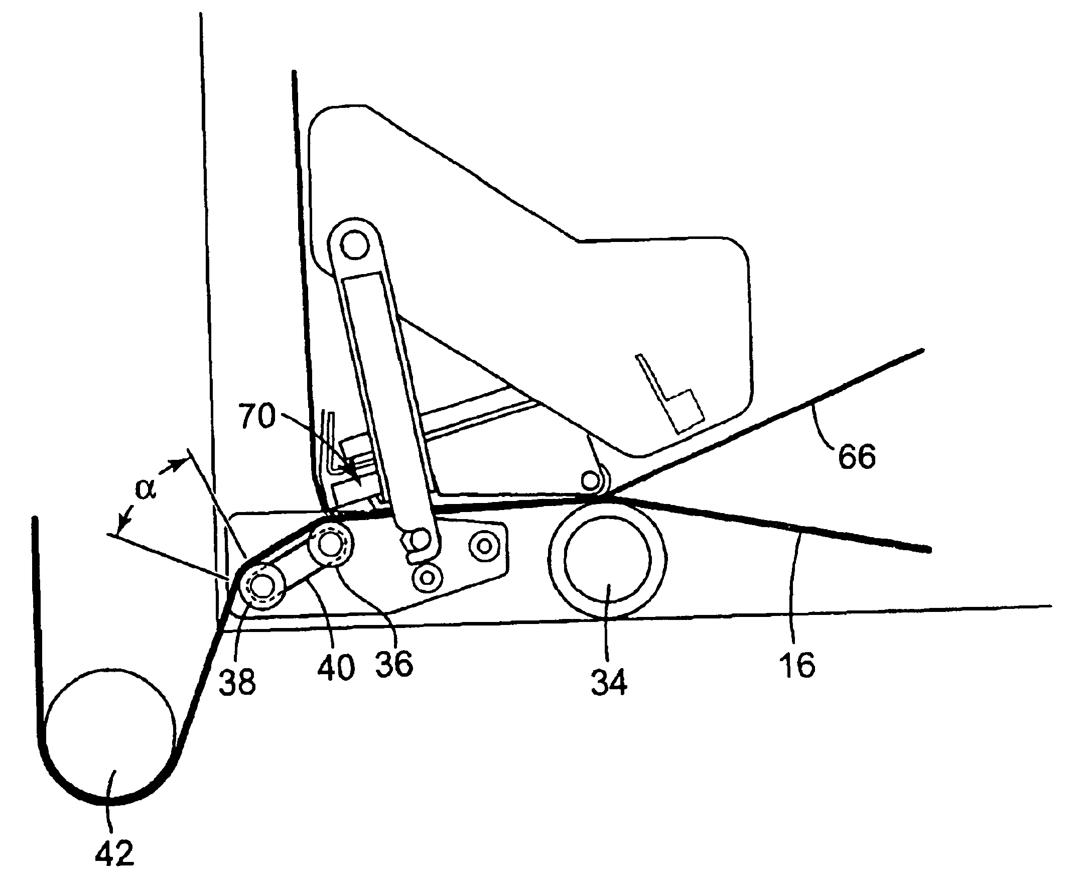
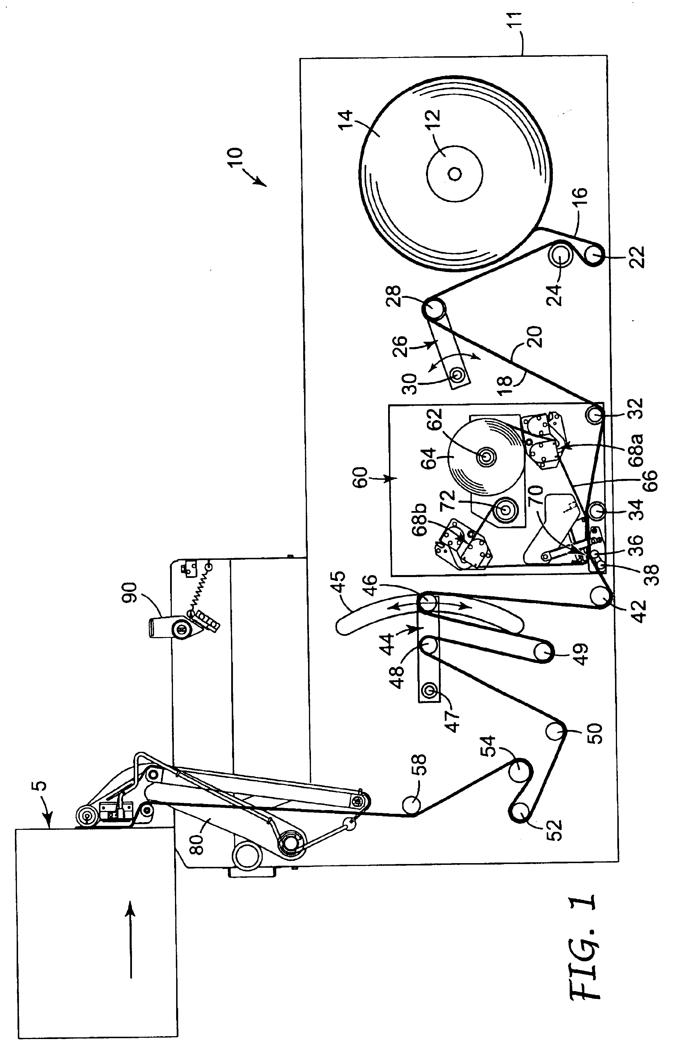
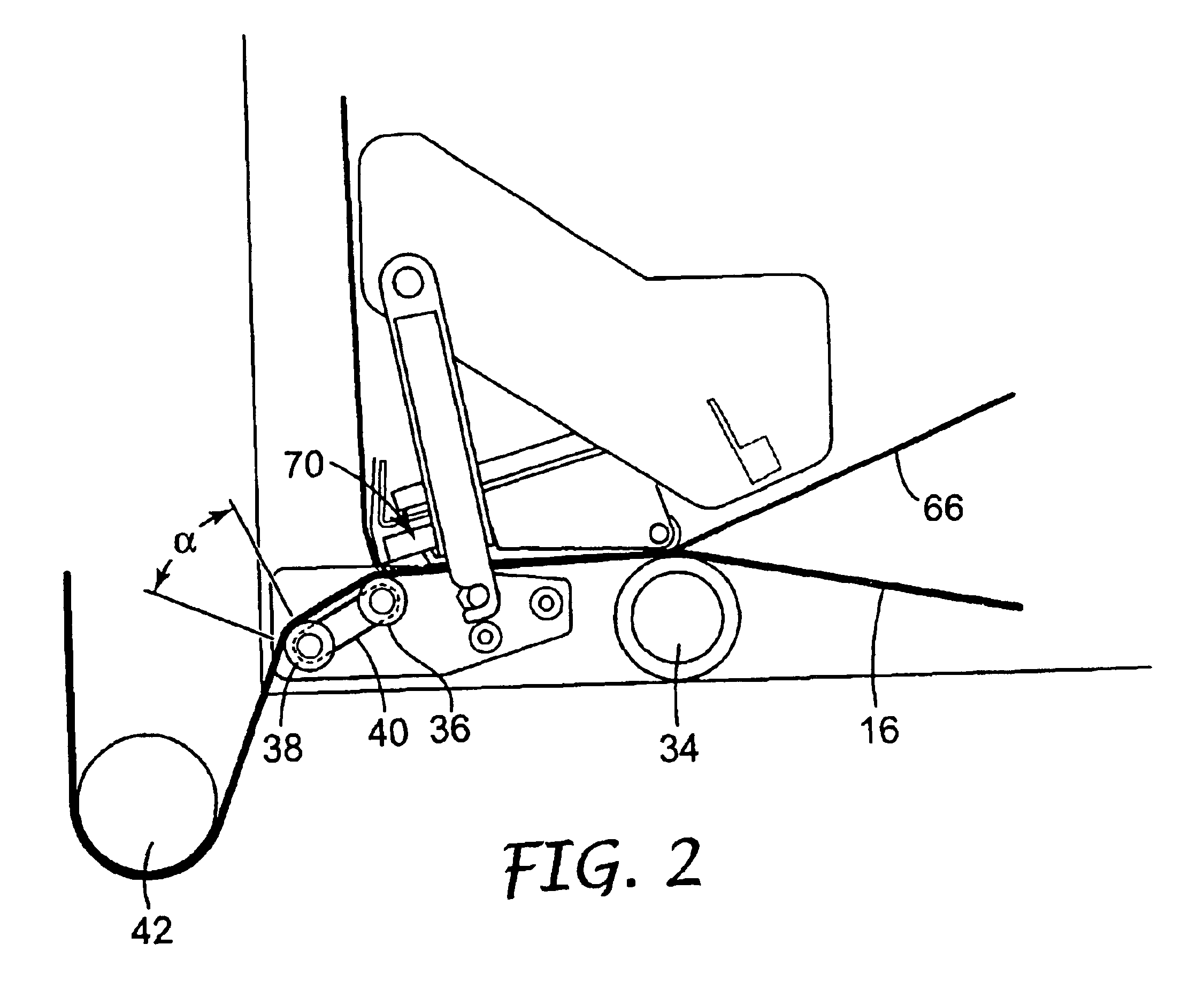
[0034]FIGS. 1 and 2 illustrate an apparatus 10 for printing on a continuous web of linerless tape for subsequent application to an article. FIGS. 3 and 4 illustrate an alternative apparatus 100 for printing on a continuous web of linerless tape for subsequent application to an article. The embodiments of the apparatus 10, 100 may be an apparatus for printing and applying tape, which prints information onto tape to form a length of printed tape and then applies the length of printed tape to an object, preferably a package or a box. The apparatus 10, 100 may vary the information printed on each length of printed tape and may vary the overall length of each length of printed tape, such that different lengths of printed tape may be produced from one supply roll of tape. The apparatus 10, 100 applies the length of printed tape onto an object or article, preferably a package or box, either while the package or box is stationary or while the box is moving (such as while the box is being cl...


PUM

PropertyMeasurementUnit
thicknessaaaaaaaaaa
wrap angleaaaaaaaaaa
thicknessesaaaaaaaaaa

Abstract

An apparatus for printing on a continuous web of linerless tape defined by a print side for subsequent application to an article. In one embodiment, the apparatus includes a support for a continuous web of linerless tape; an undriven platen roller located downstream of the support; a print head associated with the undriven platen roller, wherein the undriven platen roller directs the continuous web of linerless tape past the print head for printing on the print side thereof; and a driven roller positioned adjacent the platen roller and downstream of the print head for pulling the web of linerless tape from the platen roller. In another embodiment, the apparatus includes a support for a continuous web of linerless tape; a driven platen roller located downstream of the support; a print head associated with the platen roller, wherein the platen roller directs the continuous web of linerless tape past the print head for printing on the print side thereof; and a driven roller positioned adjacent the platen roller and downstream of the print head for pulling the web of linerless tape from the platen roller. Methods of printing indicia on a continuous web of linerless tape are also included.

Description

TECHNICAL FIELD[0001]The present invention relates to systems for handling linerless tape. More specifically, the present invention relates to a method and apparatus for handling and printing on thin, linerless label tape, such as with a linerless label printer.BACKGROUND OF THE INVENTION[0002]Containers, packages, cartons, and cases, (generally referred to as “boxes”) generally display information about the contents. This information most commonly located on the box might include lot numbers, date codes, product identification information, and bar codes. The information can be placed onto the box using a number of methods. These include preprinting the box when it is manufactured, printing this information onto the box at the point of use with an inkjet code that sprays a pattern of ink dots to form the image, or by using a flexographic ink rolling coding system. Other approaches include the use of labels, typically white paper with preprinted information either applied manually, o...

Claims


Application Information

Patent Timeline
Patent Type & Authority Patents(United States)
IPC IPC(8): B41J13/02B41J15/16B41J3/407
CPCB41J3/4075B65B51/067B41J15/165B41J13/02B41J15/04B41J3/407B41J15/16
Inventor BAKER, DANIEL D.VASILAKES, LLOYD S.
Owner 3M INNOVATIVE PROPERTIES CO
Why Eureka
Try Eureka