Shear valve apparatus and methods to improve leakage and wear

a technology of shear valves and apparatuses, applied in the field of shear valves, can solve the problems of short life of valves, frequent maintenance, and more detrimental to function, and achieve the effects of reducing the molecular adhesion of mating, reducing the coefficient of friction, and minimizing the adhesion of contaminants

Inactive Publication Date: 2010-04-29
NOVA BIOMEDICAL
View PDF9 Cites 12 Cited by
  • Summary
  • Abstract
  • Description
  • Claims
  • Application Information

AI Technical Summary

Benefits of technology

[0012]It is an object of the present invention to provide an apparatus that materially reduces the molecular adhesion of the mating, flat, interfacing surfaces of a shear valve to one another. It is another object of the present invention to provide a device that minimizes the adherence of contaminants to the interfacing surfaces. It is further object of the present invention to provide a device with a predictable fluidic seal between the mating surfaces. It is still another object of the present invention to reduce the coefficient of friction between the mating surfaces for the life of the device. It is yet a further object of the present invention to reduce the wear at the interface between the moving and stationary members of a shear valve to sustain the sealing conditions of the interfacing surfaces.
[0014]In one embodiment of the present invention, the shear valve assembly includes a stationary valve manifold having a manifold planar surface, a movable valve switch having a switch planar surface in slidable, interactive contact with the manifold planar surface forming an interactive contact junction, a surface modifying component disposed at the interactive contact junction, a drive shaft fixedly connected to the movable valve switch, an index sensor operatively coupled to one of the drive shaft and the movable valve switch, a biasing mechanism coupling the manifold planar surface of the stationary valve manifold to the switch planar surface of the movable valve switch, and a valve housing supporting the stationary valve manifold, the movable valve switch, the drive shaft and the index sensor. The stationary valve manifold contains a plurality of manifold input ports and one or more manifold output ports. The switch planar surface of the movable valve switch has a fluid switching channel capable of connecting one of the plurality of manifold input ports with one of the one or more manifold output ports. The surface modifying component provides a period of extended useful life of the manifold planar surface and the switch planar surface beyond the useful life of a pre-lubricated interactive contact junction even when ceramic components are used. The surface modifying component also reduces molecular adhesion by using very flat shear surfaces.
[0015]In another embodiment of the present invention, the surface modifying component is a diamond-like coating disposed on the manifold planar surface, the movable switch planar surface, or both. The diamond-like coating may be disposed over a major portion of the planar surface or over all of the planar surface. The diamond-like coating provides a very low coefficient of friction characterized by a molecular material arrangement that counteracts the surface adhesion phenomena, creates a very hard, wear resistant surface, and a low propensity to adhere to contaminants.

Problems solved by technology

Valves with a short lifetime require frequent maintenance to replace one or more of the sealing parts.
The downtime caused by such maintenance is undesirable as it becomes a significant expense and slows productivity.
The latter is often the more detrimental to function because of cross-contamination.
In valves, the design of surfaces to maximize lifetime is difficult to do from first principles.
This is because, as is commonly understood, the subject of wear of component parts is of considerable complexity.
The limitations of the science of tribophysics cause the development of longlife valves of the type being discussed to be driven by experimentation using a large variety of materials and surface treatments that would not necessarily be expected to produce good results.
Indeed, little is predictable in the art of making valves.
Conversely, some extremely smooth ceramic surfaces cause high wear.
Even when ceramic is used as a counterface against another ceramic rotary element, wear and friction issues persist.
This factory lubrication, however, is short lived but delays the onset of wear, abrasion, scoring, and contamination.
Additionally, in the case of ceramic valves, the very flat surfaces subject the valve faces to molecular adhesion, which causes high drag forces and even stalling during motion cycles.

Method used


Image

  • Shear valve apparatus and methods to improve leakage and wear
  • Shear valve apparatus and methods to improve leakage and wear
  • Shear valve apparatus and methods to improve leakage and wear

Examples


Embodiment Construction

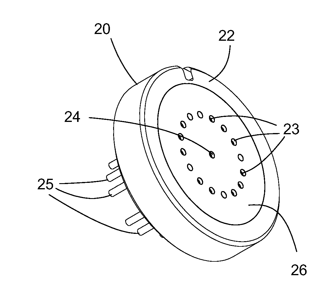
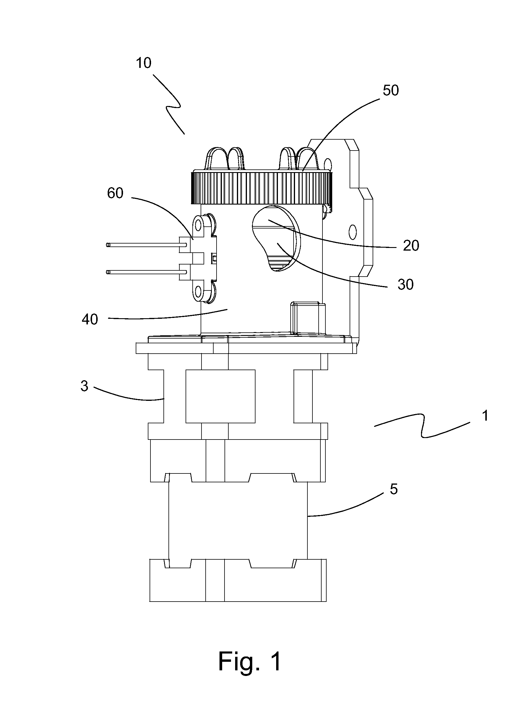
[0036]The preferred embodiment(s) of the present invention are illustrated in FIGS. 1-15. FIG. 1 Illustrates one embodiment of the rotary valve assembly 10 of the present invention assembled and connected to a drive source 1 that includes a gear box 3 and a motor 5. A section of rotary valve assembly 10 is removed to allow viewing of some of the internal components. Rotary valve assembly 10 includes a stationary valve manifold 20 and a movable valve rotor assembly 30 encased within a valve housing 40 by a retainer 50. Rotary valve assembly 10 also includes an index sensor 60 that detects a home index position of valve rotor assembly 30. Gear box 3 is used in combination with motor 5 to provide motion to valve rotor assembly 30.

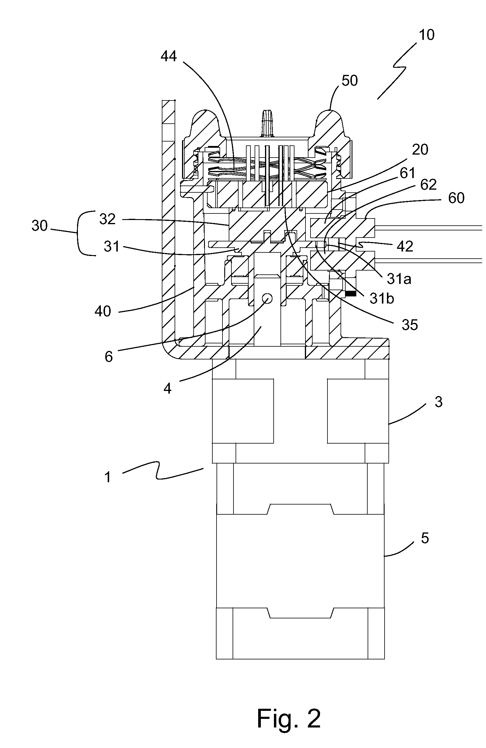
[0037]Turning now to FIG. 2, there is illustrated a cross-sectional view of the embodiment of rotary valve assembly 10 shown in FIG. 1. Valve rotor assembly 30 includes a drive shaft 31 and a valve rotor 32 fixedly connected to the drive shaft 31. Valve rotor ...


PUM


Abstract

A shear valve assembly includes a stationary valve manifold having a manifold planar surface containing a plurality of manifold input ports and one or more manifold output ports, a movable valve switch having a switch planar surface in slidable, interactive contact with the manifold planar surface forming an interactive contact junction, the switch planar surface having a fluid switching channel capable of connecting one of the plurality of manifold input ports with one of the one or more manifold output ports, a surface modifying component disposed at the interactive contact junction that provides a period of extended useful life of the manifold planar surface and the switch planar surface beyond the useful life of pre-lubricated interactive contact junction, a drive shaft connected to the valve switch, and a valve housing supporting the stationary valve manifold, the movable valve switch, and the drive shaft.

Description

BACKGROUND OF THE INVENTION[0001]1. Field of the Invention[0002]The present invention relates generally to shear valves. Particularly, the present invention relates to shear valves having improved wear and sealability of the interface between the rotating / sliding and stationary components and reducing the forces to drive the rotating or sliding component.[0003]2. Description of the Prior Art[0004]Many devices and processes require fluid switching valves for functions such as fluid selection, fraction collection, fluid redirection, stream sampling, sample injection, and the like. A common valve used in these applications is the multiport selector valve. Multiport selector valves have been known for some time and include rotary valves and linear shear valves. Rotary and linear shear valves have a very flat, rotating or linear element that moves against a similarly flat stationary member. The rotary or linear element commonly has channels used to direct the flow of fluids such as liqui...

Claims


Application Information

Patent Timeline
Patent Type & Authority Applications(United States)
IPC IPC(8): F16K3/36F16K11/16
CPCF16K25/005F16K11/0743Y10T137/86558Y10T137/86638
Inventor BICKOFF, CHARLESPETERSON, THOMAS H.
Owner NOVA BIOMEDICAL
Why Eureka
Try Eureka