
Turbine bucket airfoil cooling hole location, style and configuration

a technology of airfoil and turbine, which is applied in the direction of liquid fuel engines, vessel construction, marine propulsion, etc., can solve the problems of reducing limiting the life of the part to a predetermined number, etc., to increase the overall efficiency of the turbine, reduce the amount of air flow, and increase the life of the bulk creep par

Inactive Publication Date: 2005-06-28
GENERAL ELECTRIC CO
View PDF3 Cites 52 Cited by
  • Summary
  • Abstract
  • Description
  • Claims
  • Application Information

AI Technical Summary

Benefits of technology

"The present invention provides an air cooled bucket for a turbine with an improved cooling system that increases efficiency and lifespan of the turbine. The cooling holes are optimally arranged within the airfoil based on X, Y coordinates to meet these requirements. The size and location of the holes are determined based on pressure difference across the bucket airfoil and the heat transfer along the walls of each cooling hole. The cooling holes include first, second, and third sets with at least two holes in each set. The two holes in each set may have turbulators to enhance heat transfer. Overall, this efficient cooling scheme improves the performance and durability of the air cooled bucket for the turbine."

Problems solved by technology

Where air is used as the cooling medium, it will be appreciated that the air is derived from the compressor and therefore results in a debit to the overall efficiency of the turbine.
Insufficient cooling, however, affects bulk creep part life which in turn limits the life of the part to a predetermined number of hours of turbine operation.

Method used


Image

  • Turbine bucket airfoil cooling hole location, style and configuration
  • Turbine bucket airfoil cooling hole location, style and configuration
  • Turbine bucket airfoil cooling hole location, style and configuration

Examples


Embodiment Construction

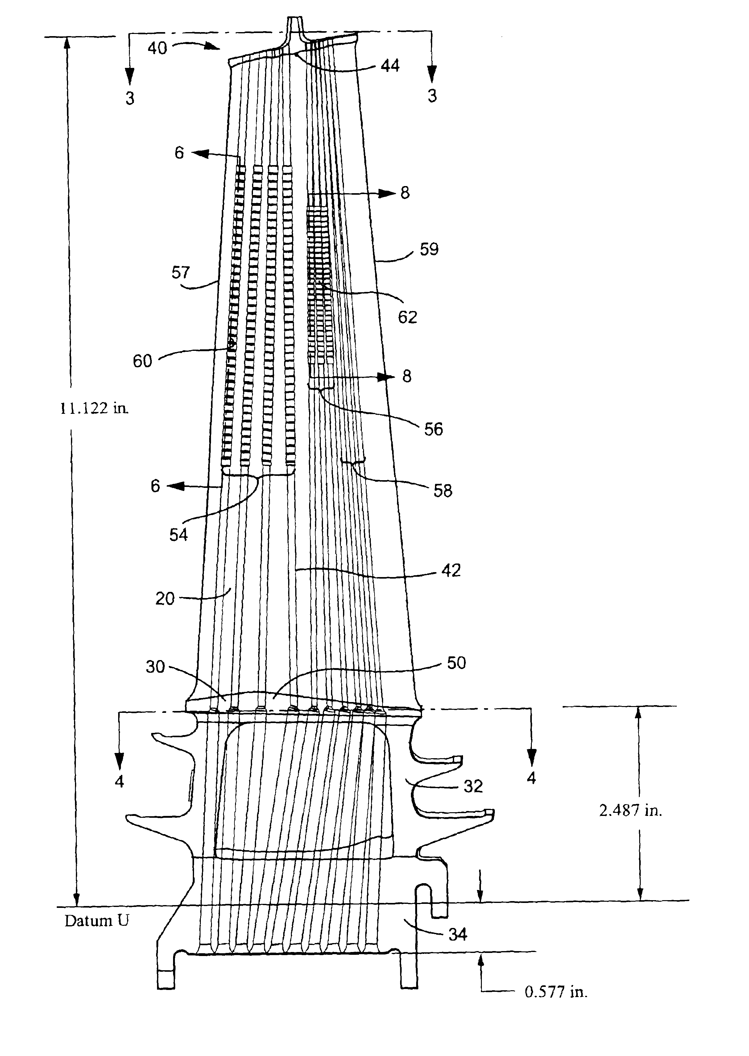
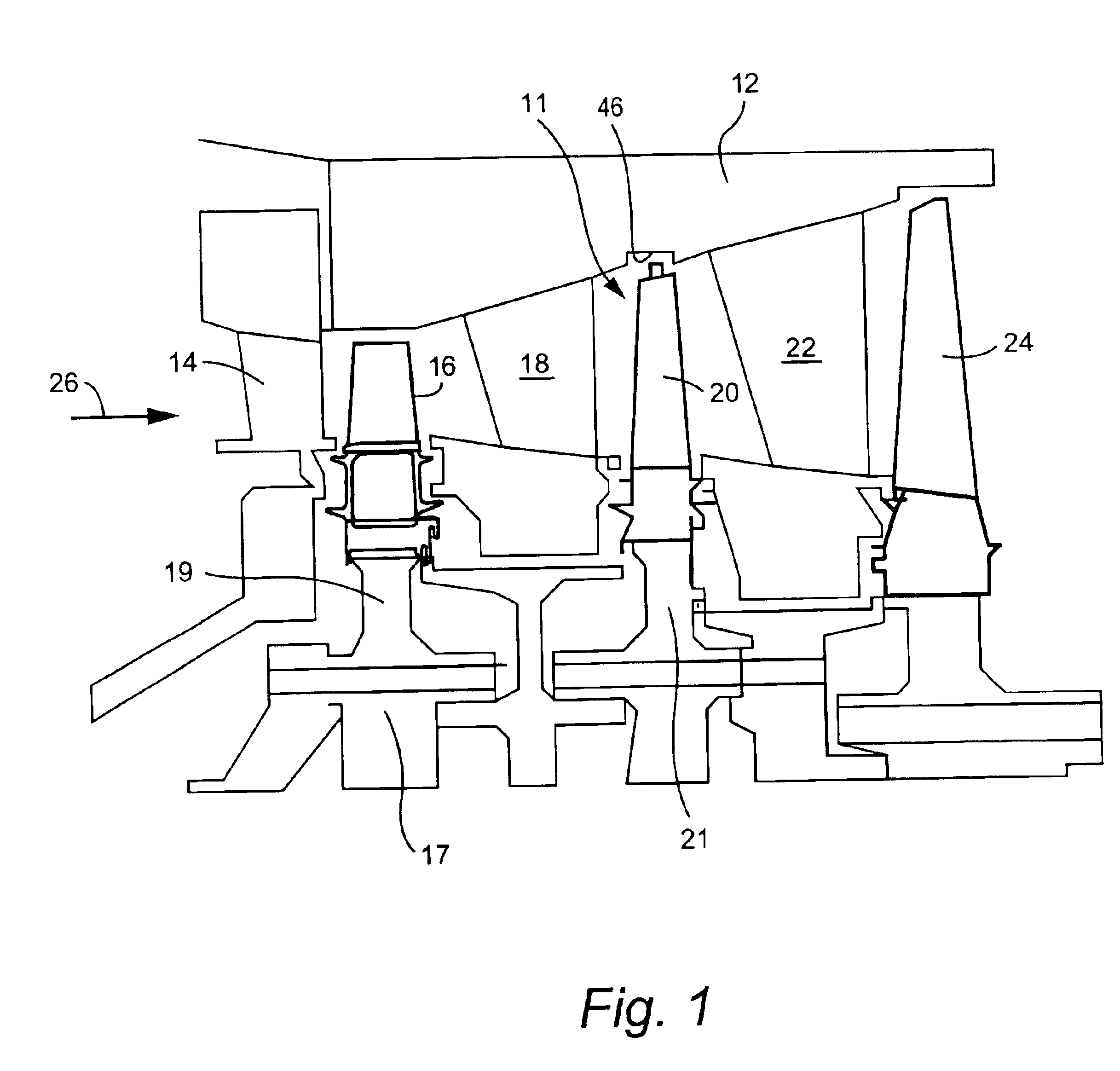
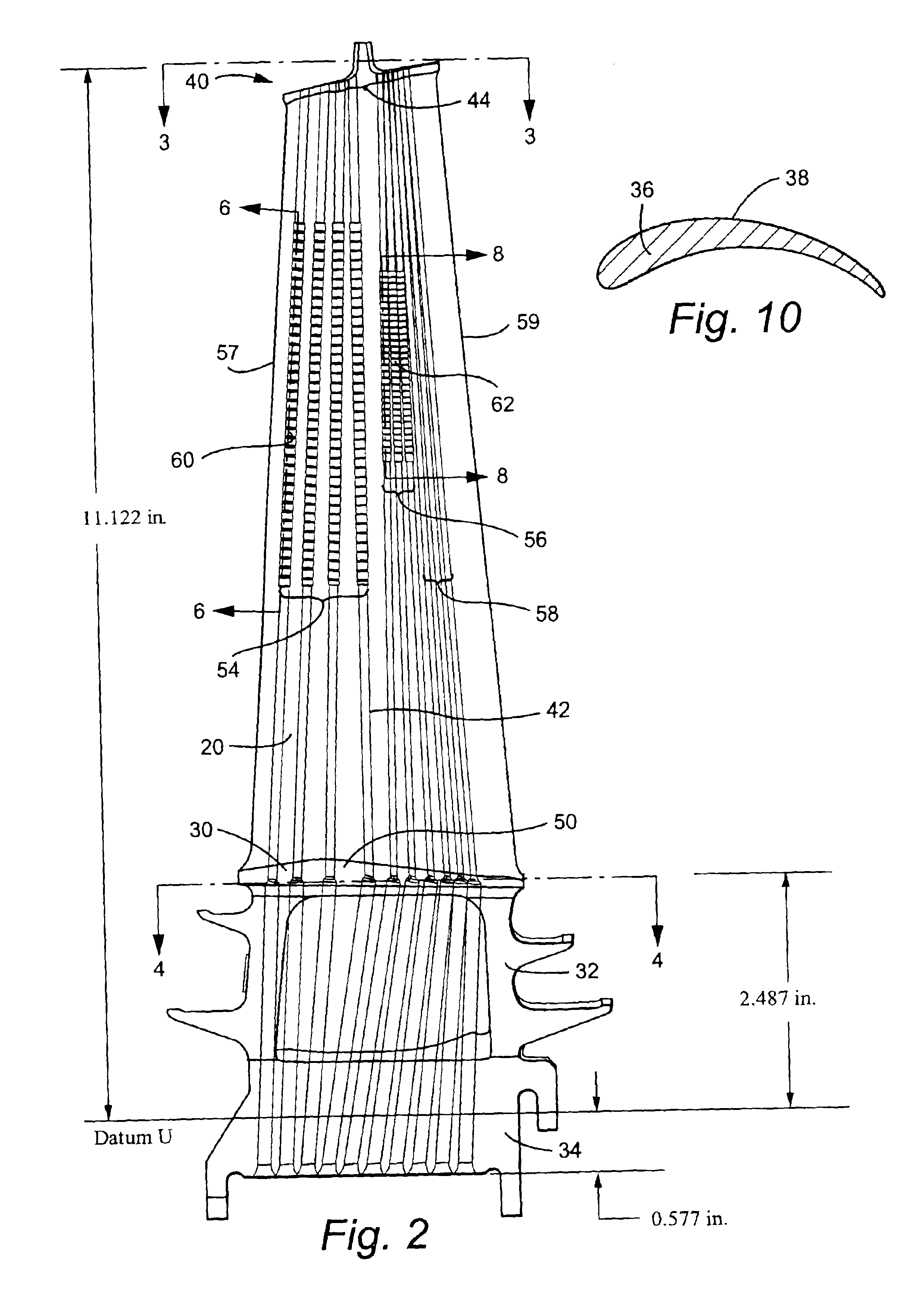
[0016]Referring now to the drawing figures, particularly to FIG. 1, there is illustrated a hot gas path, generally designated 11, of a gas turbine 12 including a plurality of turbine stages. Three stages are illustrated. For example, the first stage comprises a plurality of circumferentially spaced nozzles 14 and buckets 16. The nozzles are circumferentially spaced one from the other and fixed about the axis of the rotor. The first stage buckets 16, of course, are mounted on a turbine rotor wheel 17. A second stage of the turbine 12 is also illustrated, including a plurality of circumferentially spaced nozzles 18 and a plurality of circumferentially spaced buckets 20 mounted on a rotor wheel 21. The third stage is also illustrated including a plurality of circumferentially spaced nozzles 22 and buckets 24 mounted on the rotor. It will be appreciated that the nozzles and buckets lie in the hot gas path 10 of the turbine 12, the direction of flow of the hot gas through the hot gas pat...


PUM


Abstract

First, second and third sets of cooling holes are provided in a turbine airfoil. The first set of holes adjacent a leading edge have turbulators commencing at a predetermined distance from the root of the airfoil and terminating short of the airfoil tip. A second set of cooling holes have turbulators commencing at a greater distance from the platform than the turbulators of the first set and terminating short of the airfoil tip at a greater distance from the tip than the turbulators of the first set of holes. A third set of holes adjacent the trailing edge has smooth bores. The size, location, style and configuration of the cooling holes increases bulk creep part life and overall efficiency of the turbine.

Description

BACKGROUND OF THE INVENTION[0001]The present invention relates to an airfoil for a bucket of a stage of a gas turbine and particularly relates to a stage two bucket airfoil having an optimized number, location, style and size of cooling holes for flowing a cooling medium, e.g., air, through the airfoil.[0002]Many different types, numbers and locations of passages for flowing a cooling medium, e.g., air, through an airfoil of a turbine bucket for cooling the airfoil have been proposed and constructed. Where air is used as the cooling medium, it will be appreciated that the air is derived from the compressor and therefore results in a debit to the overall efficiency of the turbine. In prior cooling configurations for turbine buckets, compressor discharge air is supplied to the airfoil through cooling passages formed integrally within the bucket. Insufficient cooling, however, affects bulk creep part life which in turn limits the life of the part to a predetermined number of hours of t...

Claims


Application Information

Patent Timeline
Patent Type & Authority Patents(United States)
IPC IPC(8): F01D5/18
CPCF01D5/187Y02T50/673F05D2260/22141F05D2260/2212Y02T50/676Y02T50/60
Inventor TOMBERG, STEVEN E.
Owner GENERAL ELECTRIC CO
Learn More