Electronics cooling subassembly

a technology of electrical equipment and sub-assemblies, which is applied in the direction of electrical equipment contruction details, lighting and heating apparatus, air heaters, etc., can solve the problems of increasing the difficulty with which heat can be removed from heat sensitive circuits, increasing the difficulty of fan or blower to force air or other gas through heatsink fins/pins, and reducing turbulence and air boundary separation. , the effect of reducing turbulence and boundary flow separation

Inactive Publication Date: 2005-06-28
CELESTICA INT INC
View PDF47 Cites 17 Cited by
  • Summary
  • Abstract
  • Description
  • Claims
  • Application Information

AI Technical Summary

Benefits of technology

[0011]In accordance with the present invention, an electronics cooling sub-assembly comprises a gas supply, a first duct, a first heatsink adjacent a first device, a second duct, and a second heat sink adjacent a second device. The gas supply may be realized as a fan, a blower, a compressed gas supply or other gas source. The first duct provides a passageway for delivering high velocity gas from the gas supply to the first heat sink. The first duct may include a plurality of vanes for reducing the turbulence and air boundary separation within the duct. The first heatsink is in thermal communication with a first heat-producing device such as a microprocessor. In a preferred embodiment the heatsink comprises an axial shaped folded fin heatsink. The second duct is used to provide a pathway for the air leaving the first heatsink and delivers the air to the second heatsink. The second duct may also include a plurality of vanes for reducing turbulence and boundary flow separation within the second duct. The second heatsink is disposed adjacent a second device such as a circuit which provides power to the first device. The second heatsink may be realized as a folded fin linear heatsink, and the gas delivered by the second duct is directed over the linear arrangement of fins. The ducts, in a preferred embodiment are used to provide EMI protection. The ducts are made of a conductive material or of a non-conductive material which has a conductive coating. By electrically connecting the ducts to ground, the ducts perform as an EMI shield.

Problems solved by technology

Although this internal heat pathway technique increases the amount of heat which the circuits can withstand while still operating, one problem with this internal heat pathway technique is that the amount of heat generated by the circuits themselves often can exceed the amount of self-generated heat which the circuits can successfully expel as they are caused to operate at higher powers.
Furthermore, other heat generating circuit components mounted on printed circuit boards proximate the circuits of interest further increase the difficulty with which heat can be removed from heat sensitive circuits.
One problem with this approach, however, is that the amount of air or other gas which a fan or blower can force through the heatsink fins / pins is limited due to the significant blockage of gas flow pathways due to the fins / pins themselves.
Furthermore, in a densely populated printed circuit board (PCB) or multi-circuit module (MCM), other circuit components and mechanical structures required to provide or mount the PCB or module present additional blockage to gas pathways and also limits the amount of gas flow through the heatsink thus limiting the effectiveness of the heatsink.
Thus, the ability of such conventional heatsinks and heatsink fan assemblies is limited and is not sufficient to remove heat as rapidly as necessary to ensure reliable operation of state of the art devices, circuits and modules having increased thermal cooling requirements.

Method used


Image

  • Electronics cooling subassembly
  • Electronics cooling subassembly
  • Electronics cooling subassembly

Examples


Embodiment Construction

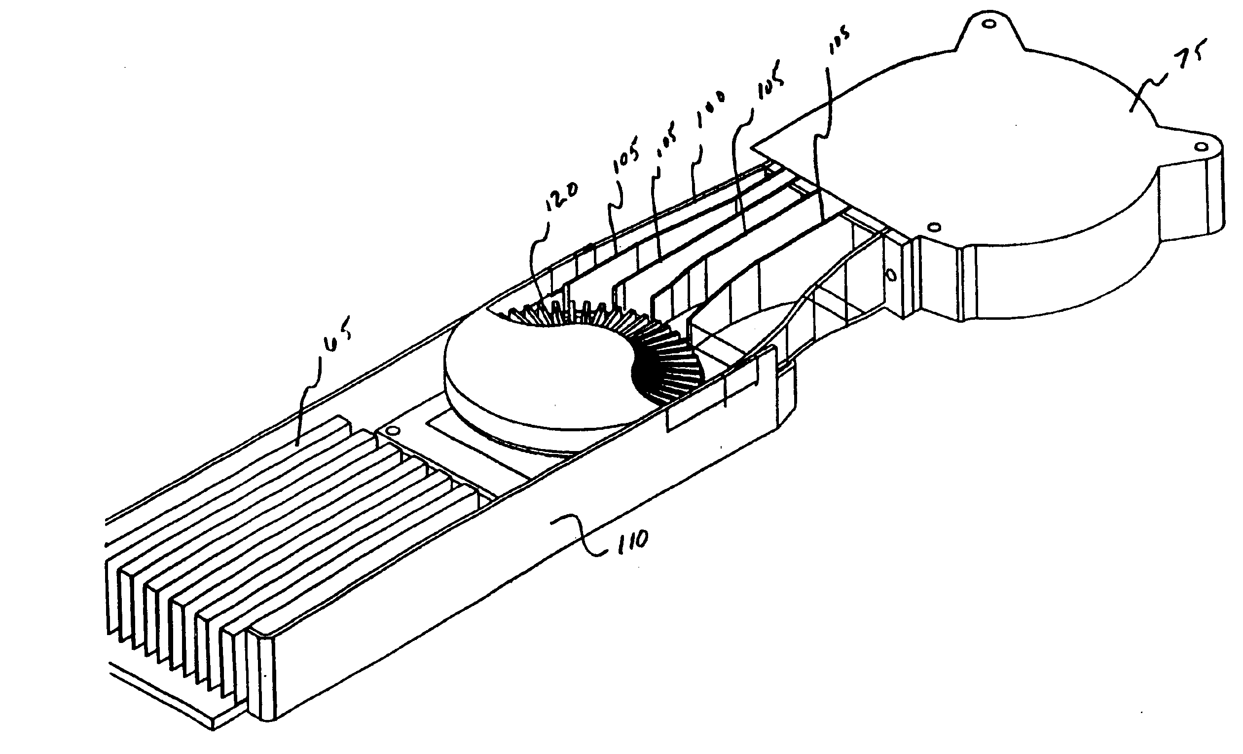
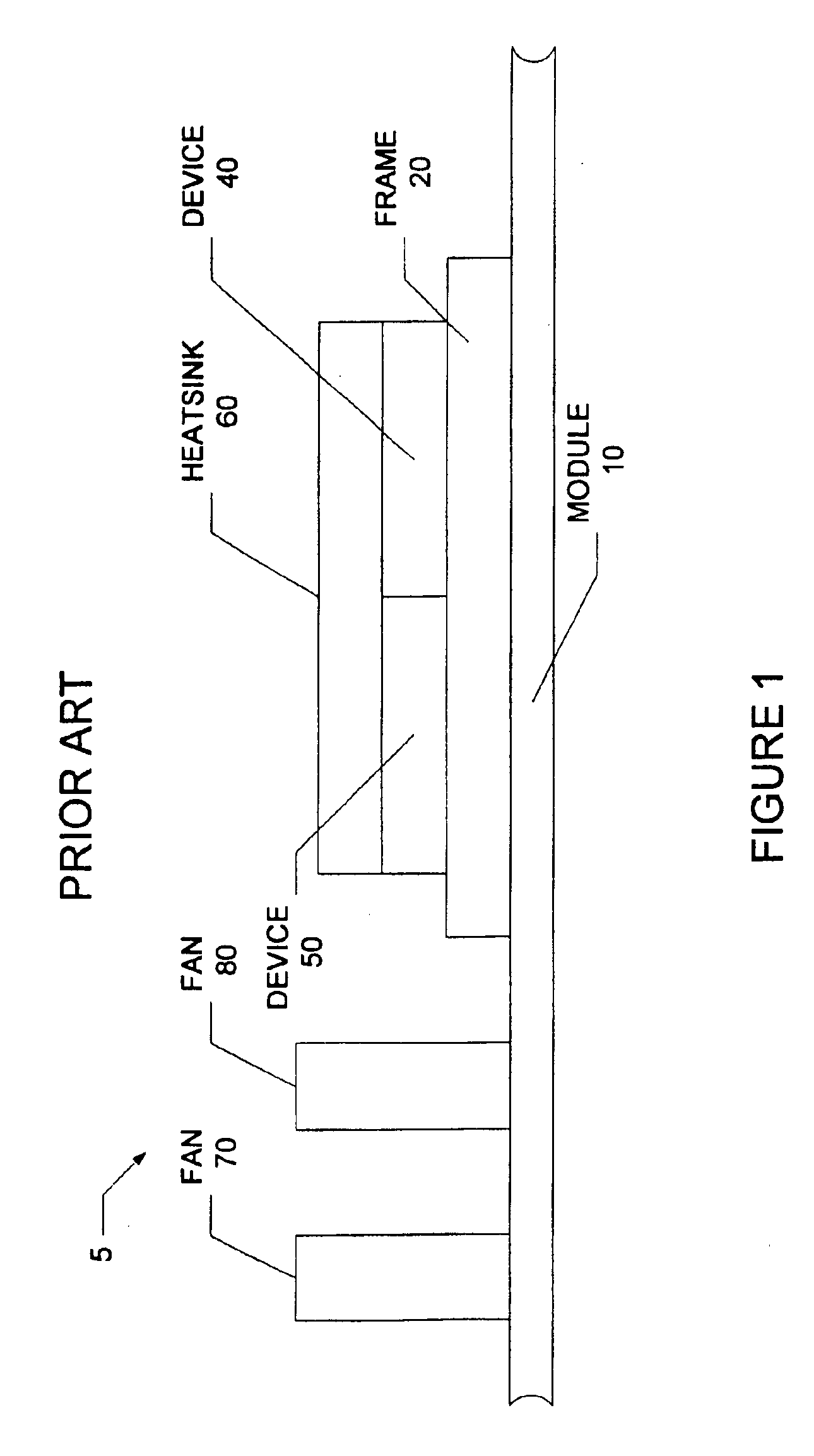
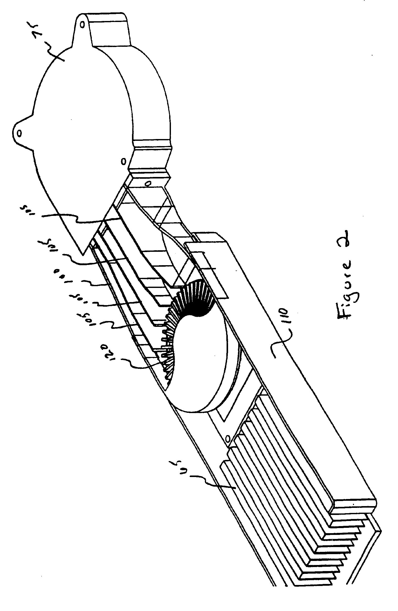
[0017]Referring now to FIGS. 1-3B in which like elements are provided having like reference designations throughout the several views, a prior art heat removal system is shown in FIG. 1, and the electronics cooling sub-assembly of the present invention is shown in FIGS. 2-3B.

[0018]As shown in FIG. 1, a prior art heat removal assembly 5 comprises a heatsink 60 coupled to a first heat producing device 50 and a second heat-producing device 40. A frame 20 is used to mount the first and second device to a module 10. In order to cool the devices 40 and 50 a pair of fans 70 and 80 are used. Fan 70 is disposed to direct an air stream to fan 80, which directs its air stream across heat sink 60. Heat sink 60 is a linear heatsink. This embodiment requires a significant amount of height, and is therefore not usable in many enclosures. Also, the heatsink 60 is a large, heavy component which has high costs associated with it. Further there is no EMI protection afforded the two devices by this con...


PUM


Abstract

A thermo-electro sub-assembly comprises a gas supply, a first duct, a first heatsink adjacent a first device, a second duct, and a second heat sink adjacent a second device. The gas supply may be realized as a fan, a blower, or a compressed gas source. The first duct provides a passageway for delivering pressurized gas from the gas supply to the first heat sink. The duct may include a plurality of vanes for reducing the turbulence and air boundary separation within the duct. The first heatsink is in thermal communication with a first heat-producing device such as a microprocessor. In a preferred embodiment the heatsink comprises an axial shaped folded fin heatsink. The second duct is used to provide a pathway for the air leaving the first heatsink and delivers the air to the second heatsink. The second duct may also include a plurality of vanes for reducing turbulence and boundary flow separation within the second duct.

Description

CROSS REFERENCE TO RELATED APPLICATIONS[0001]This application claims priority under 35 U.S.C. §119(e) to provisional patent application Ser. No. 60 / 311,214 filed Aug. 9, 2001; the disclosure of which is incorporated by reference herein.STATEMENT REGARDING FEDERALLY SPONSORED RESEARCH[0002]Not ApplicableFIELD OF THE INVENTION[0003]The present invention relates generally to electronics cooling subassemblies and more particularly to electronics cooling subassemblies for use with integrated circuits (ICs) and printed circuit boards.BACKGROUND OF THE INVENTION[0004]As is known in the art, there is a trend to reduce the size of semiconductor devices, integrated circuits and microcircuit modules while at the same time having the devices, circuits and modules perform more functions. To achieve this size reduction and increased functionality, it is necessary to include a greater number of active circuits, such as transistors for example, in a given unit area. As a consequence of this increas...

Claims


Application Information

Patent Timeline
Patent Type & Authority Patents(United States)
IPC IPC(8): H05K7/20H01L23/467H05K9/00
CPCH01L23/467H01L2924/0002H01L2924/00
Inventor BIRD, JOHNLARSON, RALPH I.NORTH, LYNE DOREBUSSIERE, PAULALLEN, AMY
Owner CELESTICA INT INC
Why Eureka
Try Eureka