Method and apparatus for metering a reducing agent for removing nitrogen oxides from exhaust gases

a technology of reducing agent and reducing agent, which is applied in the direction of valve operating means/release devices, machines/engines, separation processes, etc., can solve the problems of not only saving component costs and assembly time, but also simplifying the line course, reducing the number of components, and compact design

Inactive Publication Date: 2005-07-05
ROBERT BOSCH GMBH
View PDF16 Cites 68 Cited by
  • Summary
  • Abstract
  • Description
  • Claims
  • Application Information

AI Technical Summary

Benefits of technology

[0007]The method of the invention and the metering apparatus of the invention have the advantage over the prior art of furnishing simple ventilation and a compact design, with a reduced number of components, of a metering apparatus. A separate ventilation valve is no longer necessary, and the additional lines for such a valve are also dispensed with, making the line course simpler, and correspondingly the volume of fluid that must be heated in the metering device if correct operation is to be achieved is less, which in turn saves both energy and expense. Furthermore, the metering accuracy is improved, since pressure drops in the supply line, for instance from air inclusions or inclusions of evaporated urea-water solution, can be compensated for by adapted metering. Omitting a separate ventilation valve not only saves component costs and time in assembly, but also the entire metering apparatus can be disposed on a smaller housing block.
[0008]It is especially advantageous to provide an electrically triggerable metering pump, for instance with a stepping motor, as a feed means; this assures need-specific pumping, and by means of only a short bypass that connects the outlet of the metering pump to the suction inlet, a return of excess pumped quantities of fluid can already be assured, so that a separate return line to the urea tank can be omitted. This further simplifies the line course and correspondingly reduces the volumes of fluids that have to be heated for correct operation in the metering apparatus. The omission of a separate return line to the urea tank not only saves component costs and time in assembly, but also the entire metering apparatus can be disposed on a smaller housing block and is simpler to mount in the vehicle, since now only a single connection to the urea tank, that is, the supply line, has to be produced.

Problems solved by technology

Omitting a separate ventilation valve not only saves component costs and time in assembly, but also the entire metering apparatus can be disposed on a smaller housing block.

Method used


Image

  • Method and apparatus for metering a reducing agent for removing nitrogen oxides from exhaust gases
  • Method and apparatus for metering a reducing agent for removing nitrogen oxides from exhaust gases

Examples


Embodiment Construction

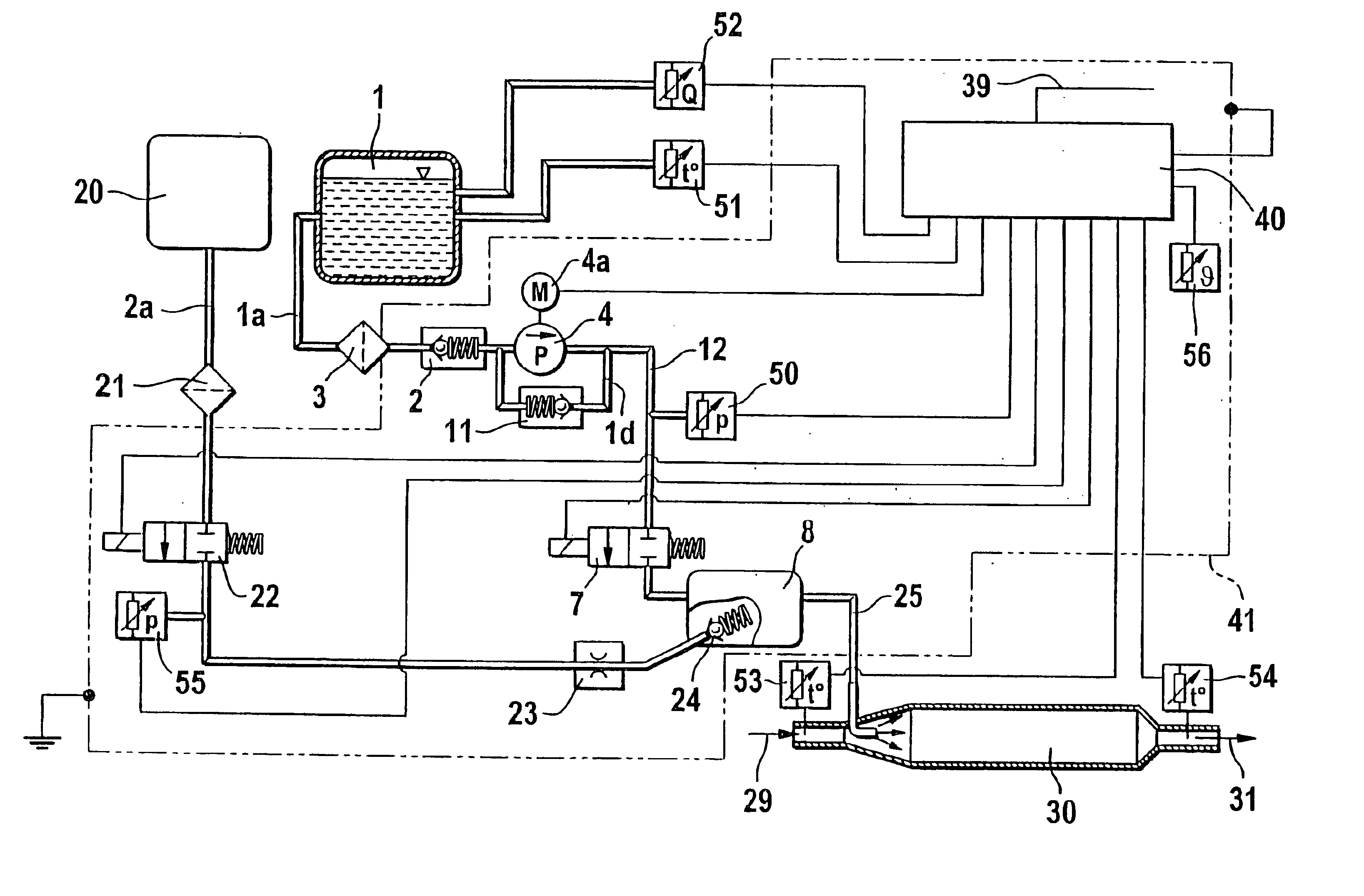
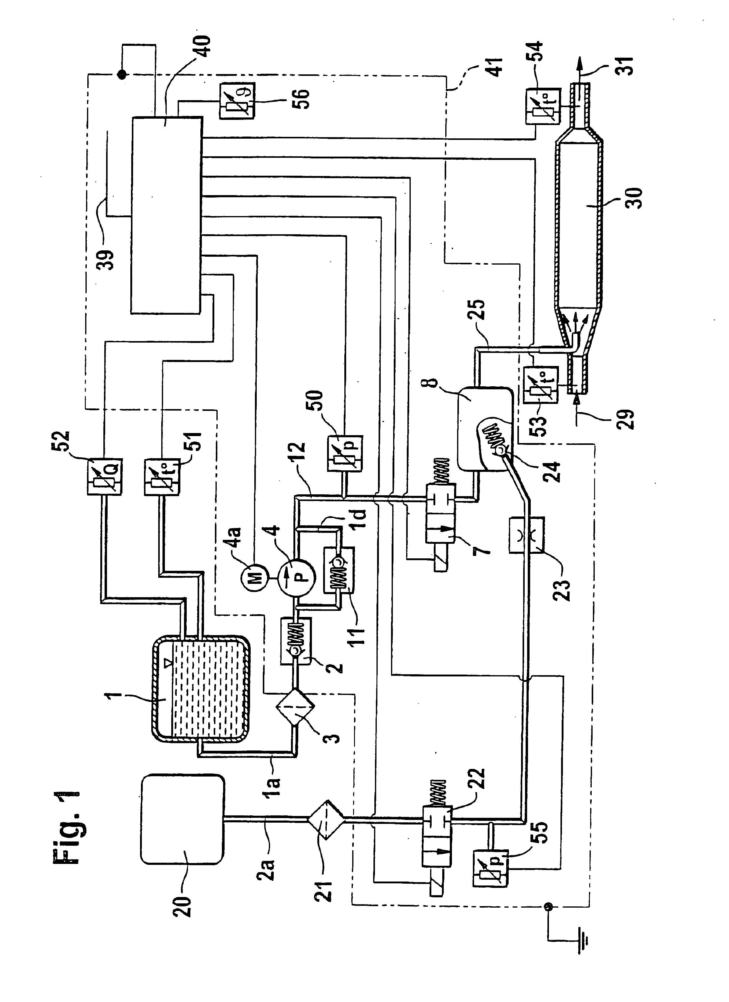
[0011]In FIG. 1, reference numeral 1 indicates a urea tank, from which a urea-water solution is carried via a urea line 1a to a filter 3 embodied as a filter screen. The filter 3 communicates via a line 12 with a check valve 2, through which the urea-water solution is aspirated by a feed pump 4, embodied for instance as a diaphragm pump, and pumped to a metering valve 7 of a mixing chamber 8. The pump 4 is rpm-controlled via a control motor 4a, in order to minimize the overflow quantity. An excess quantity pumped is returned to the intake side of the pump via a pressure limiting valve 11. Compressed air can be introduced from a compressed air tank 20 into the mixing chamber via a compressed air line 2a, which has a filter screen 21, a 2 / 2-way valve 22, a throttle 23, and a check valve 24. An aerosol line 25 leads from the mixing chamber 10 to the catalytic converter 30, which has an exhaust gas inlet 29 on one side and an exhaust gas outlet 31 on the opposite side. The urea tank 1 i...


PUM


Abstract

A method and an apparatus for metering a reducing agent in which the reducing agent is delivered, via a line and a final control element that regulates the metering, in particular a metering valve, to a catalytic converter assembly for removing nitrogen oxides from the exhaust gases, in particular of a Diesel engine; a pressure drop in the line dictated especially by gas inclusions is detected, and the line is ventilated via the final control element.

Description

CROSS-REFERENCE TO RELATED APPLICATIONS[0001]This application is a 35 USC application of PCT / DE 01 / 03621 filed on Sep. 20, 2001.BACKGROUND OF THE INVENTION[0002]1. Field of the Invention[0003]The invention is based on a method and an apparatus for metering a reducing agent, in particular a urea or a urea-water solution, within the context of catalytic exhaust gas posttreatment.[0004]2. Description of the Prior Art[0005]To attain a reduction of NOx components in exhaust gases, reduction catalytic converters have been developed especially for Diesel engines; they are typically classified as either so-called SCR catalytic converters (for “Selective Catalytic Reduction”) and storage catalytic converters. The so-called SCR catalytic converters are regenerated by the delivery of a urea and / or ammonia reducing agent, while the so-called storage catalytic converters are regenerated with hydrocarbons from the entrained internal combustion engine fuel, in so-called rich exhaust gas phases.[00...

Claims


Application Information

Patent Timeline
Patent Type & Authority Patents(United States)
IPC IPC(8): B01D53/90B01D53/94F01N3/20F01N3/08
CPCB01D53/90B01D53/9431B01D53/9495F01N3/2066F01N2610/02F01N2610/08F01N2610/14F01N2610/1466F01N2610/1473Y02T10/24Y10T137/7761Y02T10/12F01N3/20
Inventor HUBER, SVENMAYER, HANSPETERMUELLER, GERHARDOFFENHUBER, MICHAEL
Owner ROBERT BOSCH GMBH
Why Eureka
Try Eureka