Particulate filter aftertreatment of diesel engine exhaust

a technology of diesel engine exhaust and particle filter, which is applied in the direction of propulsion parts, machines/engines, electric devices, etc., can solve the problems of increasing fuel consumption, increasing the emission rate of nitrogen oxides, and increasing the emission of particulates, so as to reduce the amount of entrapped particulates

Inactive Publication Date: 2005-07-05
GE GLOBAL SOURCING LLC
View PDF8 Cites 46 Cited by
  • Summary
  • Abstract
  • Description
  • Claims
  • Application Information

AI Technical Summary

Benefits of technology

[0011]The present invention is a method and apparatus for after-treatment of the exhaust stream from a vehicle's diesel engine to remove particulate matter, by first collecting particulate matter in a filter, then burning the particulate matter to remove it from the filter. The combustion products from burning of the collected particulate matter are released to the atmosphere with a substantial reduction in the amount of entrained particulate matter. Heat to burn the collected particulate matter out of the filter, thereby regenerating the filter, is produced by an electric resistance heater powered by the vehicle's traction motors during dynamic braking of the vehicle.

Problems solved by technology

However, early fuel injection timing increases engine cycle temperature, which results in a relatively high rate of emission of nitrogen oxides.
Unfortunately, the associated retardation of the fuel injection ending time causes untimely and incomplete combustion of the fuel, which, among other things, increases the emission of particulate matter.
However, this approach increases fuel consumption.
Another approach to reducing NOx emissions is to employ exhaust gas recirculation, but this also tends to increase the amount of smoke and particulate matter in the exhaust.
However, such devices require significant changes to the structure of the vehicle to enable carrying of the urea solution, and they can result in a 3 or 4 percent reduction in fuel efficiency.
Further, when diesel engines are operated at higher altitudes, less air is introduced into the cylinders, causing the mixing of fuel and air to be less complete.
This contributes to late and incomplete combustion, which increases the emission of particulate matter and smoke.
However, this can also result in consumption of 3 or 4 percent of the fuel flow.

Method used


Image

  • Particulate filter aftertreatment of diesel engine exhaust
  • Particulate filter aftertreatment of diesel engine exhaust

Examples


Embodiment Construction

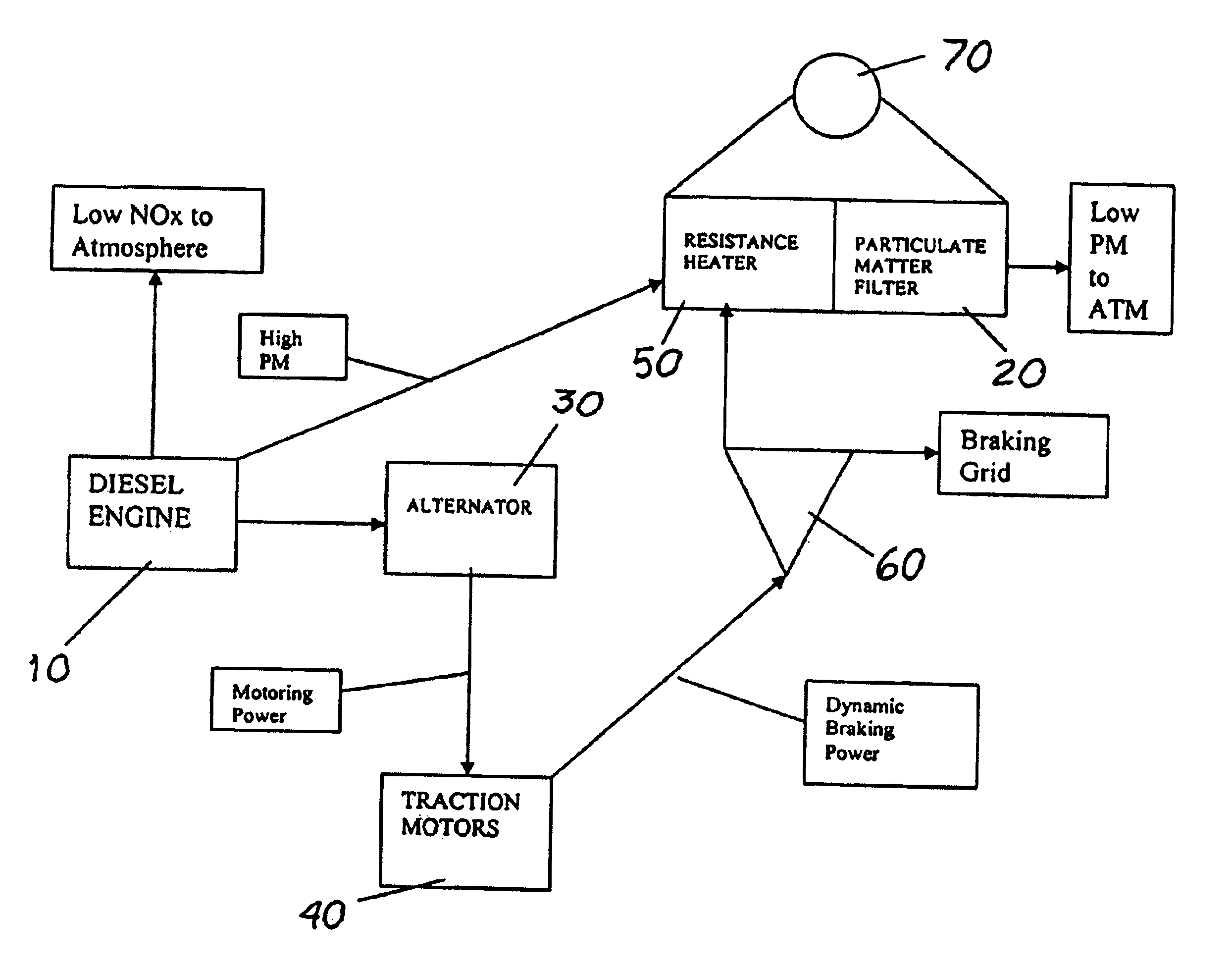
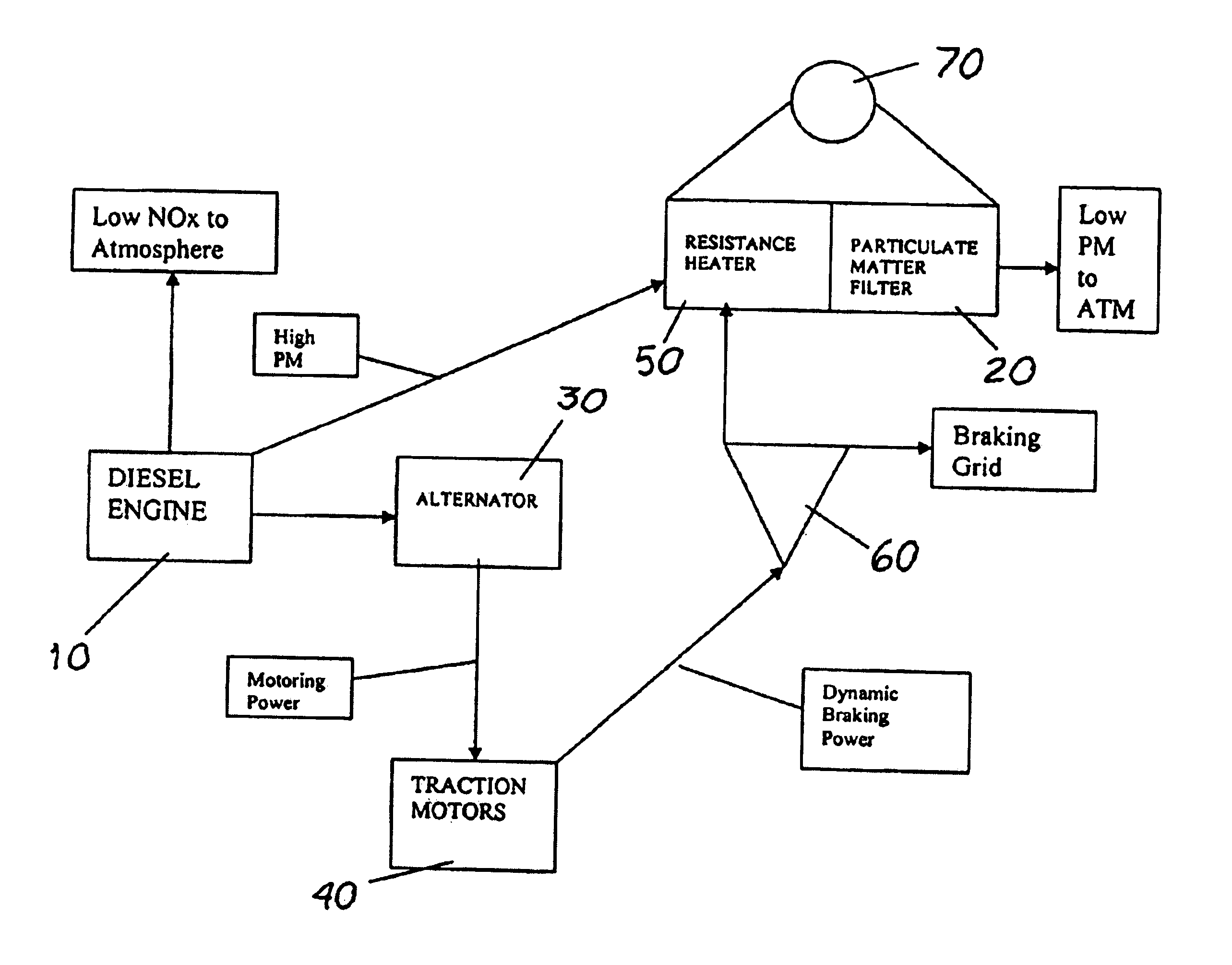
[0014]The system of the present invention can be used, for example, on a vehicle with a diesel engine in which NOx emissions are being reduced by a combination of retarded fuel injection timing, lowered manifold air temperature, and internal exhaust gas recirculation. Use of some combination of these methods would eliminate any need for after-treatment of the exhaust gas for NOx reduction, such as with lean NOx catalyst or selective catalytic reduction systems. However, a high rate of particulate matter formation will result.

[0015]As shown in the FIGURE, exhaust gas from the diesel engine 10 is routed through one or more diesel particulate matter filters (DPF) 20, where at least a substantial portion of the particulate matter is removed from the exhaust gas stream and collected in the DPF filter 20. The effluent from this DPF filter 20 is exhaust gas with significantly reduced particulate matter entrainment.

[0016]As is well known in the art, in a vehicle such as a locomotive, the di...


PUM


Abstract

A system for aftertreatment of diesel engine exhaust on a vehicle which is equipped for dynamic braking, using the electrical power generated by the dynamic braking to energize a resistor bank which incinerates particulate matter which has been collected in a particulate matter filter, thereby regenerating the filter.

Description

CROSS REFERENCE TO RELATED APPLICATIONS[0001]This application claims the benefit of the filing date of U.S. Provisional App. No. 60 / 402,391, filed Aug. 9, 2002, for “Particulate Filter Aftertreatment of Diesel Engine Exhaust”.STATEMENT REGARDING FEDERALLY SPONSORED RESEARCH OR DEVELOPMENT[0002]Not ApplicableBACKGROUND OF THE INVENTION[0003]1. Field of the Invention[0004]This invention is in the field of methods and equipment used to reduce the emission of pollutants from diesel engines, particlarly to reduce the emission of particulate matter.[0005]2. Background Art[0006]In a diesel engine, liquid fuel is injected into the cylinders, which are full of compressed air at high temperature. The fuel is broken into droplets, which evaporate and mix with the air in the cylinder to form a flammable mixture. The timing of combustion is controlled by the timing of fuel injection. Major concerns include maximizing fuel efficiency, and minimizing the emission of nitrogen oxides and particulate...

Claims


Application Information

Patent Timeline
Patent Type & Authority Patents(United States)
IPC IPC(8): F01N3/023F01N3/027
CPCF01N3/027B60K6/46B60L1/02B60L7/14B60L7/22B60L11/123B60W30/18127B60W20/1082B60L2200/26B60L2220/42B60L2240/36B60L2270/12F01N2590/11Y02T10/7077Y02T10/648Y02T10/6217B60Y2300/476F01N2590/08B60W20/16B60L50/61Y02T10/62Y02T10/64Y02T10/70Y02T10/7072
Inventor BEDAPUDI, PRAKASH
Owner GE GLOBAL SOURCING LLC
Why Eureka
Try Eureka