Ultrasonic apparatus and method for measuring the concentration and flow rate of gas

a technology of ultrasonic apparatus and flow rate, which is applied in the direction of instruments, heat measurement, specific gravity measurement, etc., can solve the problems of reducing measurement accuracy, difficult to obtain the propagation length of ultrasonic waves and the inner diameter, and affecting the propagation length and inner diameter of conduits, etc., to achieve accurate measurement of the concentration of a certain gas, simple method, and easy calibration of the apparatus

Inactive Publication Date: 2005-07-05
TEIJIN LTD
View PDF16 Cites 24 Cited by
  • Summary
  • Abstract
  • Description
  • Claims
  • Application Information

AI Technical Summary

Benefits of technology

[0012]The objective of the present invention is to provide a ultrasonic concentration measuring apparatus and method which allows the calibration of the ap

Problems solved by technology

However, the propagation length and the inner diameter of a conduit are adversely affected by the changes in the size of the conduit due to the changes in the temperature of the sample gas.
Therefore, it is difficult to obtain the propagation length of ultrasonic waves and the inner diameter of a conduit accurately, whic

Method used


Image

  • Ultrasonic apparatus and method for measuring the concentration and flow rate of gas
  • Ultrasonic apparatus and method for measuring the concentration and flow rate of gas
  • Ultrasonic apparatus and method for measuring the concentration and flow rate of gas

Examples


first embodiment

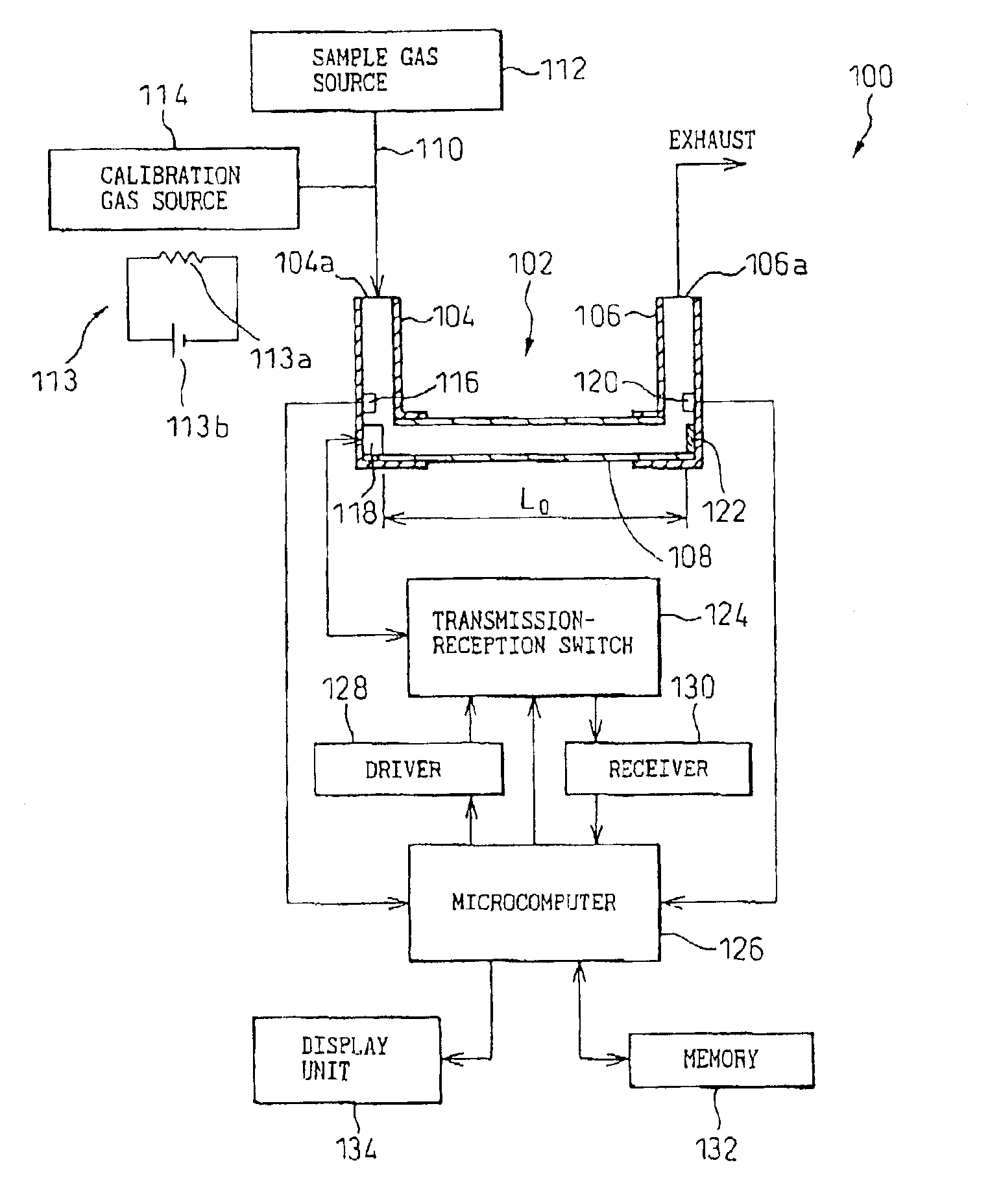
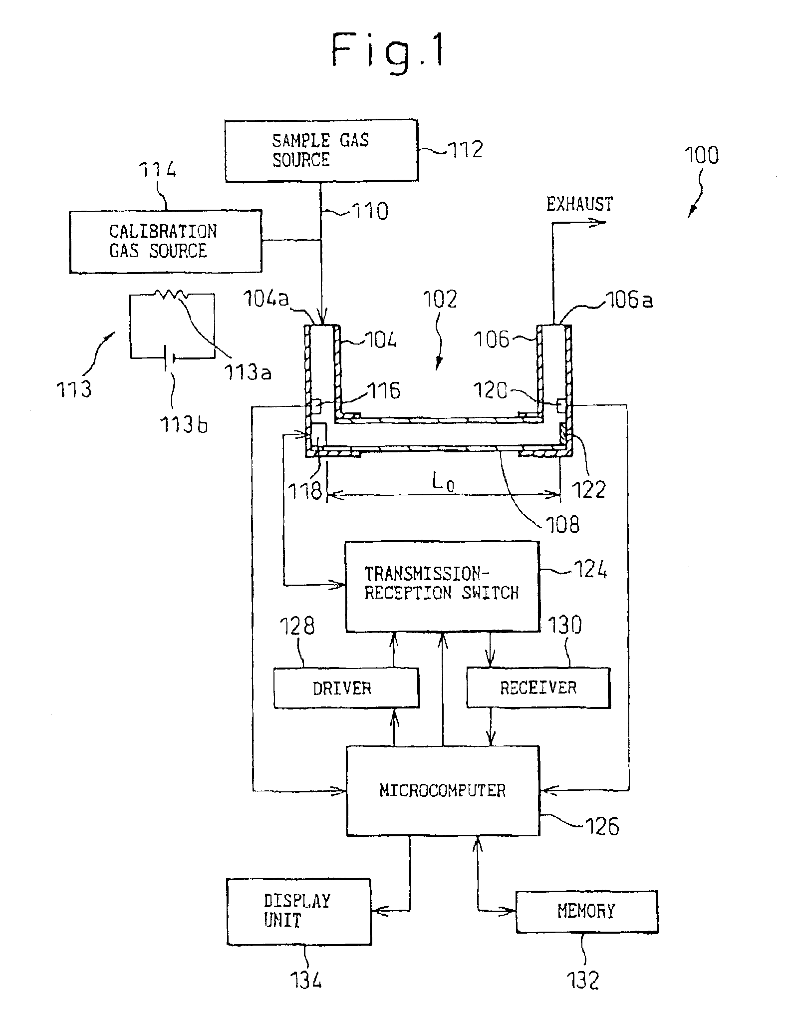
[0024]FIG. 1 shows a schematic diagram of a ultrasonic gas concentration measuring apparatus according to the present invention. The apparatus 100 includes a conduit 102 for flowing a sample gas or a calibration gas. The conduit 102 has a straight portion 108 and perpendicular portions 104 and 106 connected to the ends of the straight portion. A ultrasonic transducer 118 is fixedly provided at an end of the inside of the straight portion 108 as a ultrasonic transmission-reception device, and a reflector 122 is fixedly mounted to the other end of the inside of the straight portion 108 to face the ultrasonic transducer 118. In this embodiment, the distance between the ultrasonic transducer 118 and the reflector 122 is defined as a test length.

[0025]A transmission-reception switch 124 is connected to the ultrasonic transducer 118. The transmission-reception switch 124 switches the operation mode of the ultrasonic transducer 118 between a transmission mode in which the ultrasonic transd...

second embodiment

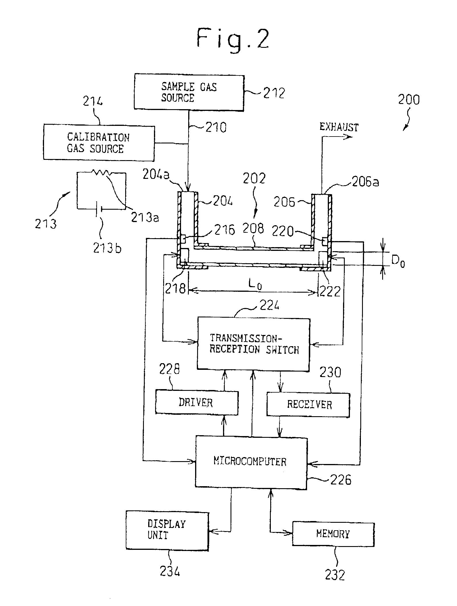
[0054]A ultrasonic gas concentration and flow rate measuring apparatus 200 includes a conduit 202 for flowing a sample gas or a calibration gas. The conduit 202 has a straight portion 208 and perpendicular portions 204 and 206 connected to the ends of the straight portion. The straight portion 208 comprises a conduit member having a circular section, the diameter of which does not changes along the longitudinal axis. A first ultrasonic transducer 218, providing a first ultrasonic transmission-reception device, is fixedly provided at an end of the inside of the straight portion, and a second ultrasonic transducer 222, providing a second ultrasonic transmission-reception device, is fixedly mounted to the other end of the inside of the straight portion to face the first ultrasonic transducer 218. In this embodiment, the distance between the first and second ultrasonic transducers 218 and 222 is defined as a test length.

[0055]A transmission-reception switch 224 is connected to the firs...


PUM


Abstract

An apparatus for measuring a gas concentration comprises a conduit through which an objective gas to be measured flows, a ultrasonic transmitting and receiving element fixed in a straight portion of the conduit and a reflecting plate fixed in the straight portion to face to the ultrasonic transmitting and receiving element. The apparatus further comprises a calibration gas source for supplying a calibration gas of which components and component ratio are preliminarily known, temperature sensors for measuring the temperature of the calibration gas flowing through the conduit, a propagation time calculating means for calculating the time period for propagation of the ultrasonic through the calibration gas in the conduit, a calibration means for calibrating the reference distance between the ultrasonic transmitting and receiving element and the reflecting plate based on the calculation results of the propagation time calculating means.

Description

TECHNICAL FIELD[0001]The invention relates to ultrasonic apparatus and method for measuring the concentration of oxygen gas in a sample gas and flow rate of the sample gas, which is supplied from an oxygen concentrator used for a medical purpose.BACKGROUND ART[0002]It is well known that the propagation velocity of ultrasonic waves through a sample gas is presented by a function of the concentration and the temperature of the sample gas. The velocity of ultrasonic waves C(m / sec) propagating through a sample gas is presented by following equation (1) with mean molecular weight M and the temperature T(K).C=(κRT / M)1 / 2  (1)Where;[0003]κ: ratio of molecular specific heat at constant volume and molecular specific heat at constant pressure[0004]R: universal gas constant[0005]Therefore measuring the velocity of ultrasonic waves C(m / sec) propagating through a sample gas and the temperature T(K) of the sample gas will provide the mean molecular weight M of the sample gas through a calculation....

Claims


Application Information

Patent Timeline
IPC IPC(8): G01N29/02G01F1/66G01N29/32G01N29/30G01N29/024G01N29/22
CPCG01F1/667G01F1/668G01N29/024G01N29/222G01N29/30G01N29/326G01N2291/0212G01N2291/0215G01N2291/02809G01N2291/02836G01N2291/044G01N2291/048G01N2291/102G01F1/66
Inventor FUJIMOTO, NAOTOSHI
Owner TEIJIN LTD
Why Eureka
Try Eureka