Method and apparatus for controlling well pressure while undergoing subsea wireline operations

a wireline operation and well pressure technology, applied in the field of wireline operations, can solve the problems of unfavorable high-pressure line operation, system never being applied safely, and difficulty in controlling well pressure at deep depths, so as to save on the cost of casing rental, increase safety, and take up more room

Inactive Publication Date: 2005-07-05
BOYDS BIT SERVICE +1
View PDF6 Cites 36 Cited by
  • Summary
  • Abstract
  • Description
  • Claims
  • Application Information

AI Technical Summary

Benefits of technology

[0014]An advantage of the present invention includes increased safety since the work string is concentrically located within the riser and sealed within the annular preventer. Another advantage is that the operator can pump a kill fluid through the control head or side entry device if an unexpected pressure develops within the inner portion of the lubricator.
[0015]Yet another advantage is the method disclosed herein requires a minimum amount of casing to be run while the remainder of the work sting is drill pipe. This results in a savings on the cost of the rental of casing. Casing is larger and bulker than drill pipe, and therefore, takes up more room on these exotic locations. Thus, another advantage is the method employed uses less casing and therefore, takes up less space and requires less support such as vessels to transport and stage the process.
[0016]Therefore, it is an object of the present invention to provide a system for conducting wireline operations in subsea conditions at the floor of the seabed, so as to prevent any undue pressure from rupturing the riser between the rig floor and the subsea floor.
[0017]It is a further object of the present invention to provide a method of conducting wireline operations deep within subsea conditions, without subjecting the riser between the rig floor and the seabed to blowout pressures.
[0018]It is a further object of the present invention to provide a wireline subsea blowout preventer control head assembly system used in subsea conditions for allowing wireline work to be conducted at the sea floor, under pressure, so as to allow pressure testing of components of the system without fear of compromising the integrity of the riser which may cause a catastrophic oil or gas spill into the body of water. These, as well as many other objects, will be apparent from a reading of the following description.

Problems solved by technology

Although the use of the side entry sub is common for drilling, the system has never been applied safely on subsea blowout preventers which are located in deep water, since controlling the well pressure at deep depths is very difficult.
It would be quite impractical to run a high-pressure line from the rig floor to the BOP stack on the Gulf floor to tie into the annular preventer so that one could pressure test the wireline.
The BOP's need to be pressure tested, but the riser cannot take high pressure tests above the blowout presenters, or it would rupture and expel hydrocarbons into the Gulf waters.

Method used


Image

  • Method and apparatus for controlling well pressure while undergoing subsea wireline operations
  • Method and apparatus for controlling well pressure while undergoing subsea wireline operations
  • Method and apparatus for controlling well pressure while undergoing subsea wireline operations

Examples


first embodiment

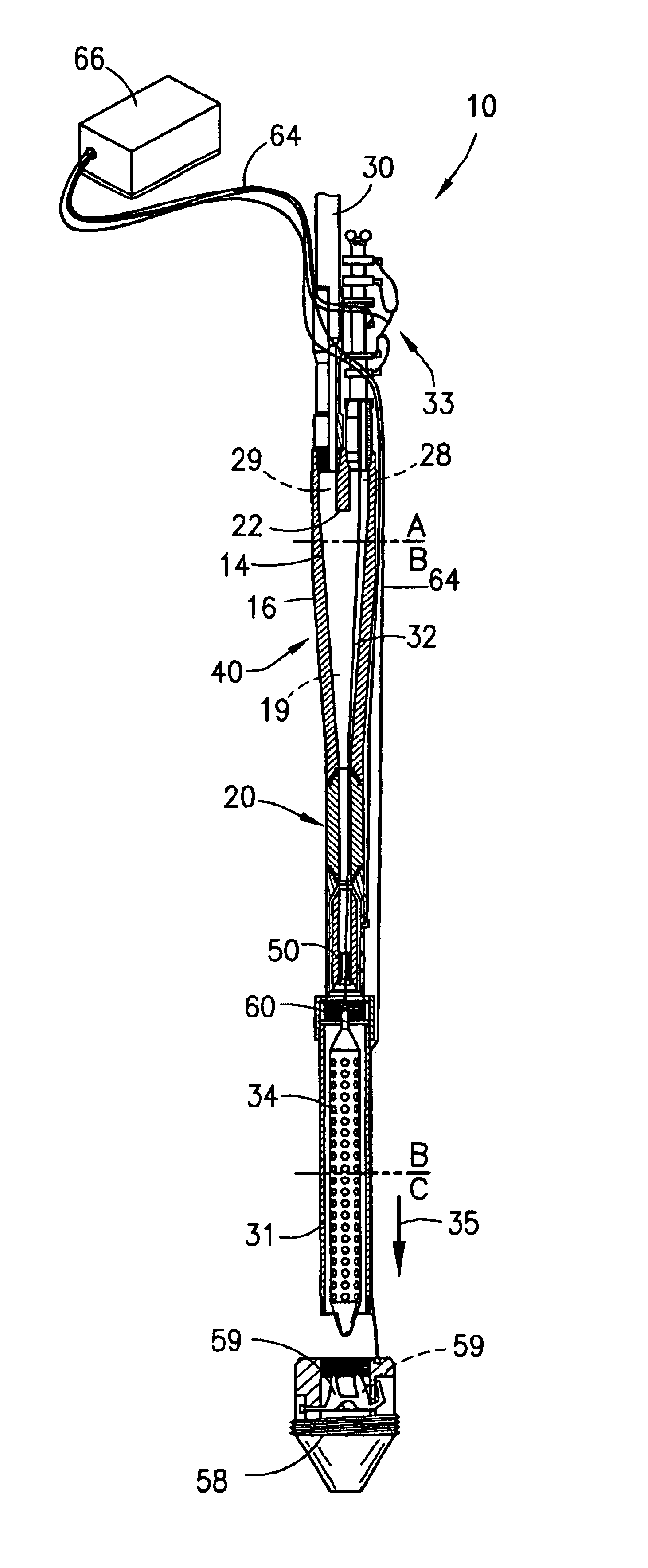
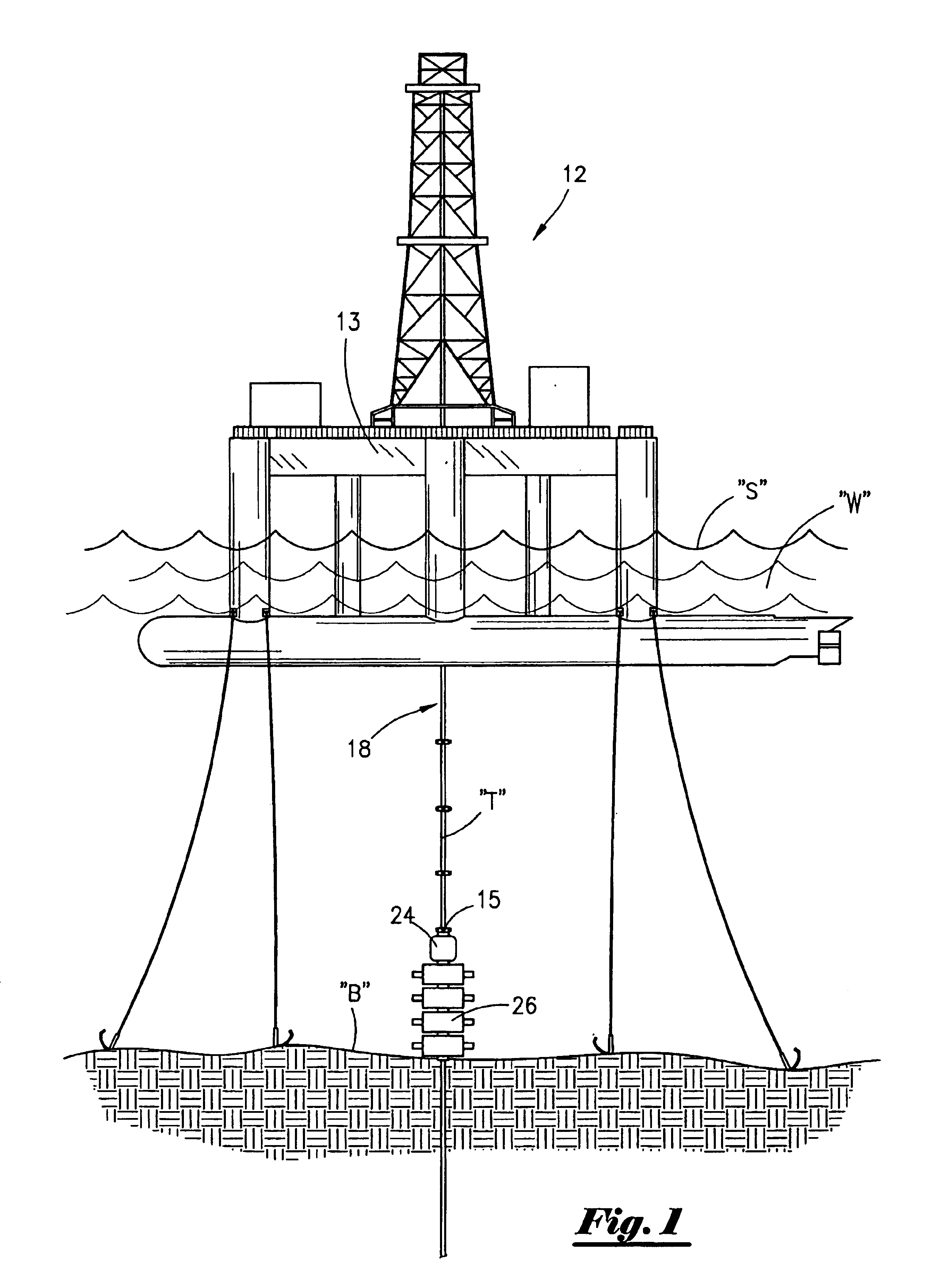
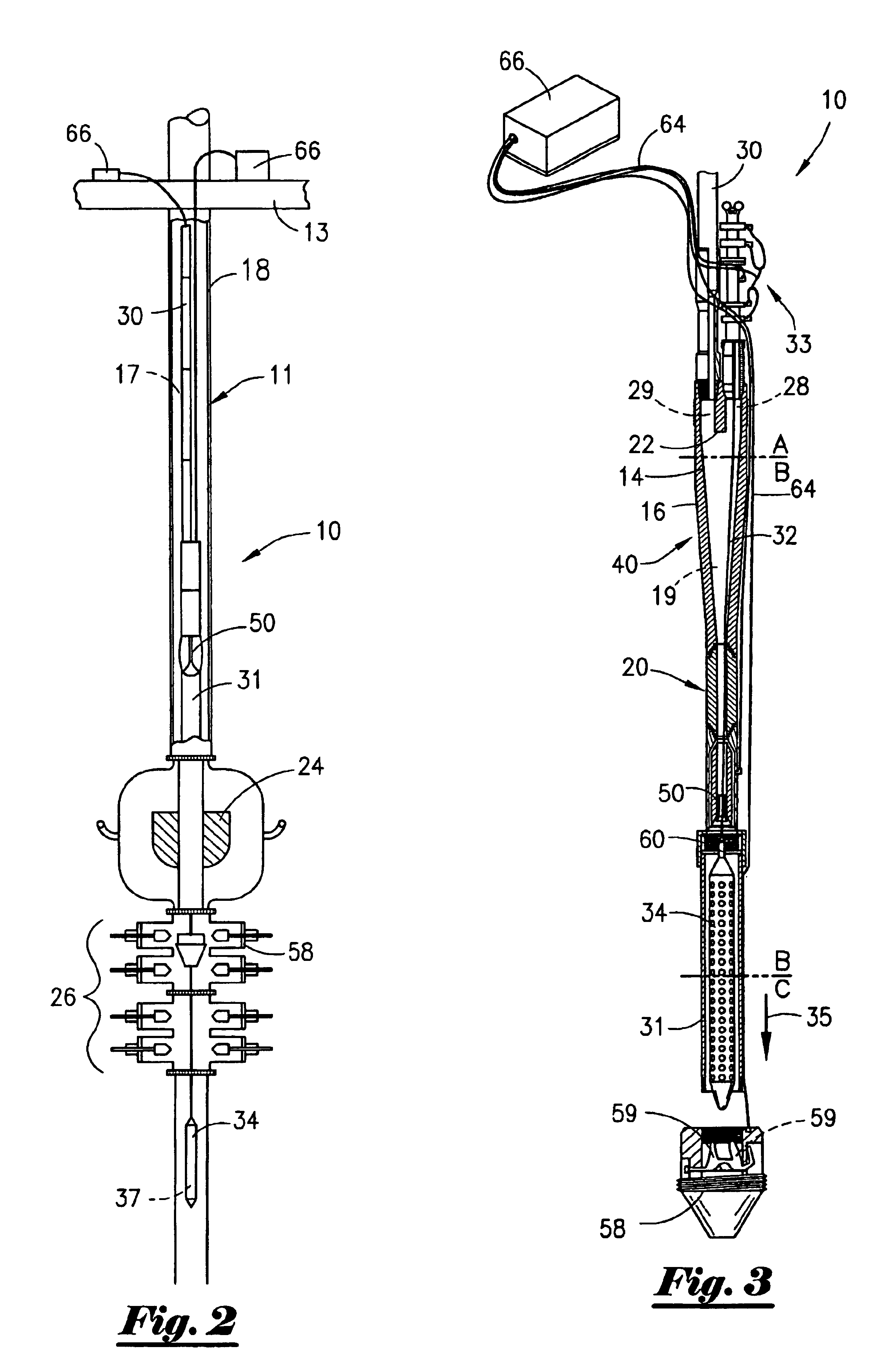
[0034]FIGS. 1-7 illustrate the system of the wireline subsea blowout preventer control head assembly (assembly) of the present invention. The assembly is illustrated by the numeral 10, as seen in FIGS. 2, 3 and 4A-4C. Prior to discussing assembly 10 in detail, reference is made to FIG. 1, where there is illustrated in cross section a typical rig 12 positioned on the surface S of a body of water W, such as the Gulf of Mexico. The rig would include an extended riser 18, comprising a plurality of tubular elements T, stacked and flanged with bolts to define the entire riser 18 extending from the rig floor 13, to the seabed B. For purposes of this discussion the rig 12 may be in water as deep as 10,000 feet, or even deeper, and the riser 18 would therefore be 10,000 feet in overall length. Such a riser is normally some 20 inches in diameter, but can only withstand internal pressures of around 2000 lbs. before the riser would rupture. This, of course, must be avoided since such a rupture ...

second embodiment

[0043]Referring now to FIGS. 8 through 13, a second embodiment, which is the preferred embodiment of this application, will now be discussed. As set out in FIG. 8, this second preferred embodiment utilizes a typical drilling rig and subsea components positioned within a deep water environment during exploration, drilling and completion operations. It should be noted that like numbers appearing in the various figures refer to like components. Thus, the rig 12 is positioned within a body of water W. The rig 12 has a rig floor 13 where a rotary table 102 is operatively contained thereon as is well understood by those of ordinary skill in the art. The rig 12 may be a drill ship or a semi-submersible rig, even though the invention herein disclosed is applicable to all types of rigs.

[0044]As seen in FIG. 8, a riser 18 extends from the rig floor 13 to the sea bed B. More particularly, the lower end 15 of the riser 18 is attached to the annular preventer 24, and extending from the annular p...


PUM


Abstract

Method and assembly for conducting wireline operations in a deep, subsea location. The method includes providing a rig on the surface of a body of water, having a riser extending from the rig floor to the sea floor; an annular preventer positioned on the end of the riser on the sea floor; a plurality of blowout presenters positioned below the riser to prevent a blowout into the riser; and, a wireline subsea blowout preventer control head. A lubricator is lowered into the riser, with the control head attached thereto, and wherein the wireline tool is disposed within the control head. The lubricator is position within the annular preventer. Wireline operations may then be conducted. If a blowout occurs during wireline operations, any pressure would be prevented from entering the riser, and would be contained by the control head.

Description

CROSS-REFERENCE TO RELATED APPLICATIONS[0001]This is a continuation in part application of Ser. No. 10 / 119,172 filed on 9 Apr. 2002 now abandoned which is a continuation application of Ser. No. 09 / 571,787 filed 16 May 2000, now U.S. Pat. No. 6,367,553.BACKGROUND OF THE INVENTION[0002]1. Field of the Invention[0003]The apparatus and method of the present invention relates to wireline operations in the recovery of oil and gas. More particularly, the present invention relates to a method and apparatus for controlling well pressure while undergoing wireline operations on subsea blowout preventers on the subsea floor.[0004]2. General Background of the Invention[0005]In conducting wireline operations, many types of tools are positioned on the lower end of a wireline, which is a steel cable or the like, lowered into the well bore in order to undertake certain tests downhole. Because in the past there have been difficulties in undertaking wireline work with the potential hazard of blowouts ...

Claims


Application Information

Patent Timeline
Patent Type & Authority Patents(United States)
IPC IPC(8): E21B33/03E21B33/072E21B33/06E21B33/035
CPCE21B33/035E21B33/06E21B33/072E21B33/038
Inventor BOYD, ANTHONY R.
Owner BOYDS BIT SERVICE
Why Eureka
Try Eureka