
Medical tool carrier

a technology for medical tools and carriers, applied in the field of medical tool carriers, can solve the problems of reducing the chance of contamination

Inactive Publication Date: 2005-07-05
FOUNTAIN CYNTHIA
View PDF9 Cites 7 Cited by
  • Summary
  • Abstract
  • Description
  • Claims
  • Application Information

AI Technical Summary

Benefits of technology

[0008]The instant invention overcomes the limitations of the prior art described above. It is a storage box that can be attached to a patient's bed rail. The box has a number of slots, cavities, and hooks that can be used to hold a wide range of medical equipment. Unlike the devices mentioned above, this device allows practitioners to hold items larger than tubes and more specific than medicine jars in one container. Moreover, the container has shaped cavities that make sorting of the equipment easy and fast. The shaped cavities also ensure that the proper equipment is used and placed in the proper location to reduce the chance of error in the administration of various treatments. Moreover, this organization of equipment decreases the chance of contamination. For example, oxygen tubes will not fall on the floor. It eliminates the possibility of spillage from the nasogastric suction tubing. Finally, it is safer in that the unit has a place for holding sharps, which reduces the possibility of them being left on a bed or at the bedside.

Problems solved by technology

Moreover, this organization of equipment decreases the chance of contamination.

Method used


Image

  • Medical tool carrier
  • Medical tool carrier
  • Medical tool carrier

Examples


first embodiment

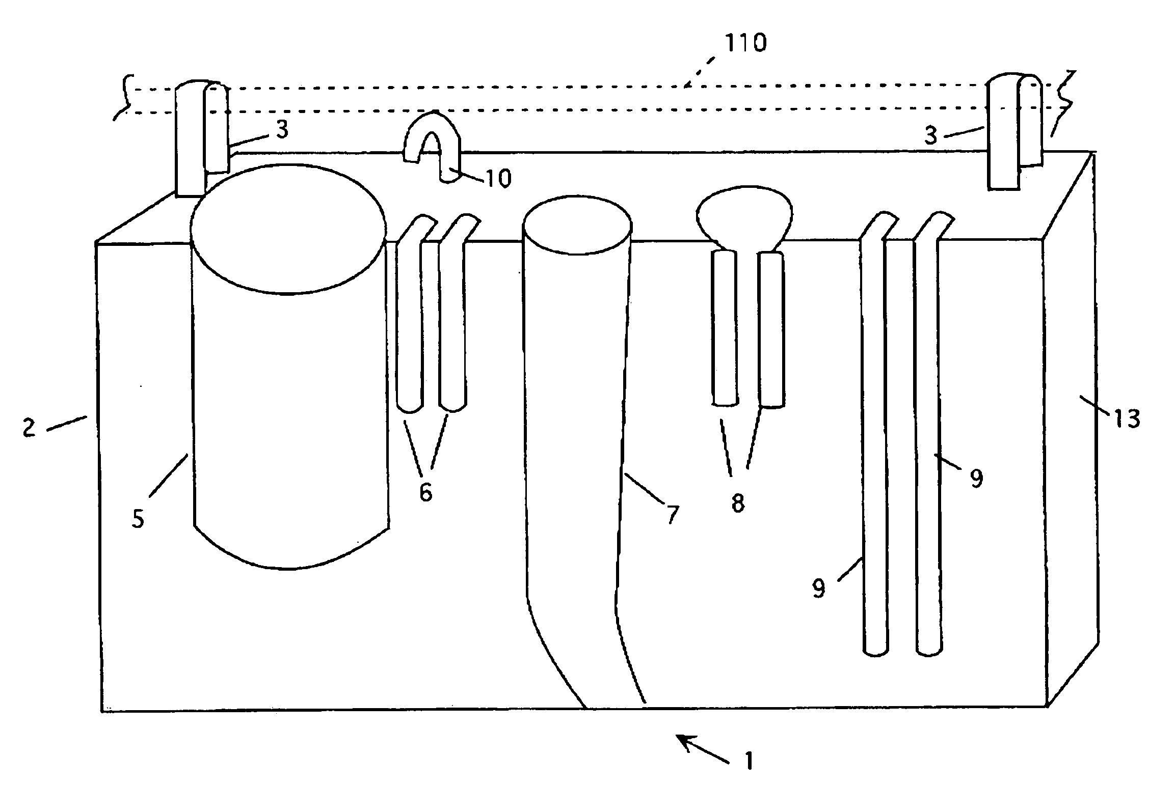
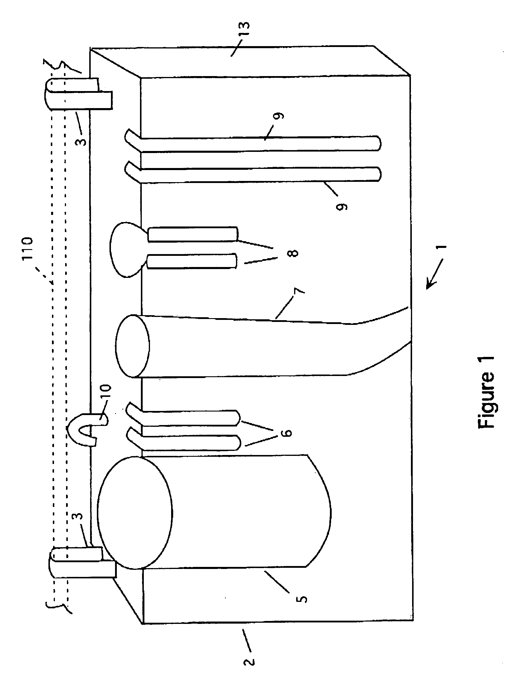
[0015]Referring now to FIG. 1, the invention is shown. In this view the equipment carrier 1 is in the basic form. It consists of a formed housing 2 that has two support straps 3 attached to the top as shown. The support straps can have hook and loop type fasteners, clips or buckles, all of which are common to the art. The straps 3 are used to hang the carrier 1 from a side rail 110 of a patient's bed.

[0016]The equipment carrier 1 has a number of formed cavities. The first cavity 5 is a cylindrical (or square) opening that is used to hold lab tubes, syringes and caps, and other miscellaneous items. Next to the first cavity is a pair of formed slots 6. These slots are used to hold IV tubes. Next to them, is a conical cavity 7. This cavity has a curved base and is used to hold an oral suction instrument. Next to that is a cavity 8 used for Keofeed tubing and cap. Next to that is a pair of slots 9 used to hold nasogastric suction tubing. Finally, on the top of the housing 2 is a hook 10...

second embodiment

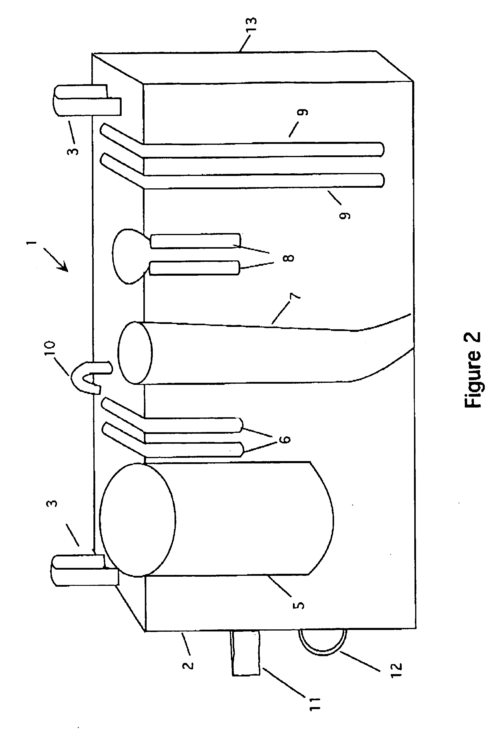
[0017]FIG. 2 shows a In this view, the basic elements remain as described above. In this embodiment, an additional strap 11 is placed on the side. Also, a ring 12 that can hold either a urinal or a foley bag. All other aspects of the device are the same as before.

[0018]FIG. 3 shows an optional storage pouch 20 that can be used with either embodiment. The storage pouch 20 is placed on the side 13 of the housing 2. Two straps 21 are used to attach the storage pouch to the housing. In the preferred embodiment, the straps 21 are lengths of hook and loop type fastener that attach to mating hook and loop type fasteners 22 (see FIG. 4) that are placed on the top of the housing as shown.

[0019]The storage pouch has two pockets 23 and 24 is designed to hold a nurse call control 100 in one of the pockets and a portable phone 101 or TV remote control in the other. Of course these pockets can be used for other items as well. FIG. 4 shows a top view of the storage pouch 20 loaded with a nurse ca...


PUM


Abstract

A storage box that can be attached to a patient's bed rail. The box has a number of slots, cavities, and hooks that can be used to hold a wide range of medical equipment. Unlike the devices mentioned above, this device allows practitioners to hold items larger than tubes and more specific than medicine jars in one container. Moreover, the container has shaped cavities that make sorting of the equipment easy and fast. Finally, the shaped cavities also ensure that the proper equipment is used and placed in the proper location to reduce the chance of error in the administration of various treatments.

Description

CROSS REFERENCE TO RELATED APPLICATIONS[0001]Not ApplicableSTATEMENT REGARDING FEDERALLY SPONSORED RESEARCH AND DEVELOPMENT[0002]Not ApplicableBACKGROUND OF THE INVENTION[0003]1. Field of the Invention[0004]This invention relates to medical tool carriers and particularly to medical tool carriers attached to patient's bedsides.[0005]2. Description of the Prior Art[0006]The medical field has become a user of many technologies. These technologies use a vast array of equipment. Devices must be brought into a patient's room and set up for use in a convenient and efficient way so that nurses and technicians can readily make use of the equipment as needed. To that end, several devices have been developed to hold various pieces of equipment in hospital rooms. Examples of these devices are found in the following U.S. Patents: U.S. Pat. No. 6,012,585, which describes a caddie for sickroom use for storing medicine containers, thermometers, cups and the like that has a base, a back panel which ...

Claims


Application Information

Patent Timeline
IPC IPC(8): A61B19/02A61B19/00
CPCA61B19/0256A61B2019/0258A61B2019/028A61B50/22A61B2050/301A61B50/20
Inventor FOUNTAIN, CYNTHIA
Owner FOUNTAIN CYNTHIA
Learn More