Card reader comprising an energy-saving system

a card reader and energy-saving technology, applied in the field of smart card readers, can solve the problems of system complexity, limited battery life time, and non-zero current consumption, and achieve the effect of suppressing the power consumption of a microprocessor, straightforward and low cos

Inactive Publication Date: 2005-07-05
STMICROELECTRONICS SRL
View PDF15 Cites 9 Cited by
  • Summary
  • Abstract
  • Description
  • Claims
  • Application Information

AI Technical Summary

Benefits of technology

[0013]An object of the present invention is to provide a straightforward and low cost approach for suppressing power consumption of a microprocessor in a smart card reader when a smart card is not in the reader.

Problems solved by technology

The main drawback of such a reader 1 is that it has a non-zero consumption of current when not in use, and a limited battery life time.
However, the system requires a certain degree of complexity for having the power supply circuit react to the active signal delivered by the card detector.

Method used


Image

  • Card reader comprising an energy-saving system
  • Card reader comprising an energy-saving system
  • Card reader comprising an energy-saving system

Examples


first embodiment

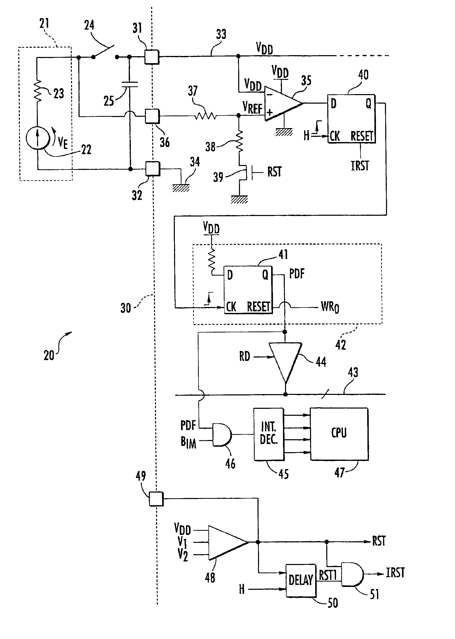
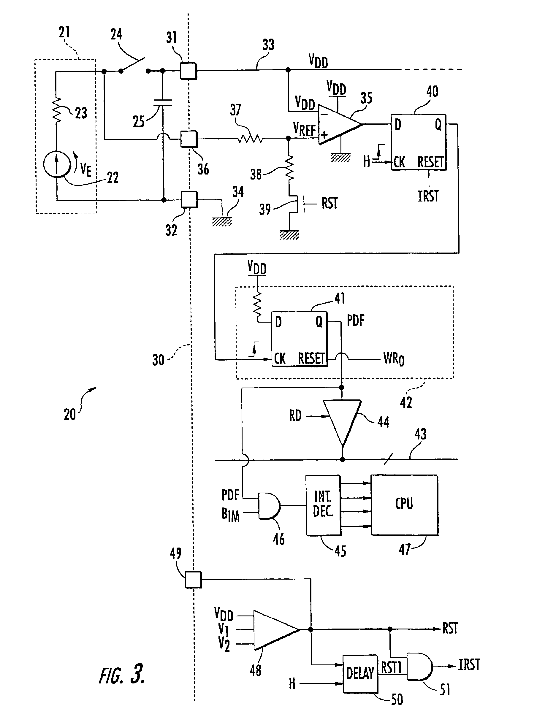
[0037]the detection means will now be discussed with reference to FIG. 3. The detection means comprises a comparator 35, the negative input of which is connected to the power supply terminal 31 and receives the power supply voltage VDD. The positive input of the comparator 35 receives a reference voltage VREF.

[0038]Advantageously, the reference voltage VREF is produced by the voltage VE, without passing through switch 24, using a special terminal 36 of the microprocessor 30 directly connected to the anode of battery 21. Here, the reference voltage VREF is picked up at the middle point of a voltage divider bridge comprising two resistors 37 and 38. Resistor 37 is connected to terminal 36 and resistor 38 is connected to ground via a switch 39, for example, a MOS transistor. This switch 39 is driven by a reset signal RST from the microprocessor 30, as described later on.

[0039]The output of the comparator 35 is applied to the D input of a synchronous D flip-flop 40. The clock input CK o...

second embodiment

[0049]the detection means will now be discussed with reference to FIG. 5. The illustrated reader 60 comprises different means for detecting opening of the switch 24. The comparator receiving the reference voltage VREF is not used. The terminal 36 of the microprocessor 30 is connected to the anode of the battery 21 via a second travel end switch 61, which opens and closes at the same instant as the switch 24. For example, switch 61 is placed adjacent to the switch 24 in the housing.

[0050]Terminal 36 is connected to the D input of flip-flop 40 via an inverter circuit 62, such as an inverting gate or a trigger with hysteresis. When switch 61 is open, the input of the inverter circuit 62 is held in the low state by a resistor 63. The resistor 63 has a very high value and is connected to ground. Except for these differences, the other components of reader 60 are the same as those of reader 20 of FIG. 3, and will not be further described.

[0051]When switch 61 opens, the output of the inver...


PUM


Abstract

A smart card reader includes a housing for receiving a smart card, a microprocessor, and a connector for connecting the microprocessor to the received smart card for establishing communications therebetween. A voltage source provides a power supply voltage to the microprocessor based upon the smart card being received in the housing. The smart card reader further includes a first switch interposed between the voltage source and a power supply terminal of the microprocessor. The first switch is closed when the received smart card is at an end of travel in the housing so that the power supply voltage is provided to the microprocessor, and is opened when the received smart card is no longer at the end of travel in the housing so that the power supply voltage is not provided to the microprocessor.

Description

RELATED APPLICATION[0001]This application is a continuation of Ser. No. 10 / 059,444 filed on Jan. 29, 2002, now U.S. Pat. No. 6,772,946, which is a continuation of International application no. PCT / FR00 / 02129, filed Jul. 25, 2000, the disclosures of which are hereby incorporated by reference in their entirety.[0002]The present application is a continuation of International Application No. PCT / FR00 / 02129 filed on Jul. 25, 2000, the entire disclosure of which is being incorporated herein by reference.FIELD OF THE INVENTION[0003]The present invention relates to electronic devices, and more particularly, to a smart card reader.BACKGROUND OF THE INVENTION[0004]An example smart card reader 1 known as a viewer is illustrated in FIG. 1. A viewer type card reader 1 generally comprises a small size case or housing 2, a display 3 and a slot 4 for receiving the smart card 5. Due to the reduced size of the case 2, only an end of the card 5 is received. This type of reader enables, for example, th...

Claims


Application Information

Patent Timeline
Patent Type & Authority Patents(United States)
IPC IPC(8): G06K7/00G06K17/00
CPCG06K7/0013G06K7/006G06K7/0069G06K7/0086
Inventor RUAT, LUDOVICFERRAND, OLIVIERGAILHARD, BRUNO
Owner STMICROELECTRONICS SRL
Why Eureka
Try Eureka