System and method for verifying optical character recognition of optical code reads

a technology of optical character recognition and optical code, applied in the direction of instruments, sensing by electromagnetic radiation, sensing by mechanical means, etc., can solve problems such as inaccurate inventories, faulty reads, and processing of faulty data

Inactive Publication Date: 2005-07-05
SYMBOL TECH LLC
View PDF10 Cites 38 Cited by
  • Summary
  • Abstract
  • Description
  • Claims
  • Application Information

AI Technical Summary

Problems solved by technology

While the ability of the RFID reader to read a tag from an object while the object is typically located remote from the reader, not necessarily in a line-of-sight of the reader, and without orienting the tag in a particular orientation is advantageous in many applications, it is very possible that the reader might read a tag associated with an object that was not intended to be processed by the reader, resulting in a faulty read.
In applications in which the read tag data is further processed, a faulty read will result in processing of faulty data, causing undesirable results, such as inaccurate inventories, charging an incorrect price for a consumer item, processing an unintended library book, charging a toll to an unintended vehicle, etc.
Furthermore, noise, due to environmental conditions including moisture in the air and intervening objects, may corrupt data being read by the reader.
Also susceptible to faulty reads due to lack of accuracy and reliability are optical code readers that image an optical code and use optical character recognition (OCR) to recognize the code and generate a corresponding textual code.
Recognition of each character has an associated error rate.
The error rate associated with a string of characters is compounded by the error rate that corresponds to each character in the string.
When the above factors are not ideal, an OCR module performing the OCR processing may have difficulty differentiating between several interpretations of individual characters and may independently select the interpretation representing the most probable textual code.

Method used


Image

  • System and method for verifying optical character recognition of optical code reads
  • System and method for verifying optical character recognition of optical code reads
  • System and method for verifying optical character recognition of optical code reads

Examples


Embodiment Construction

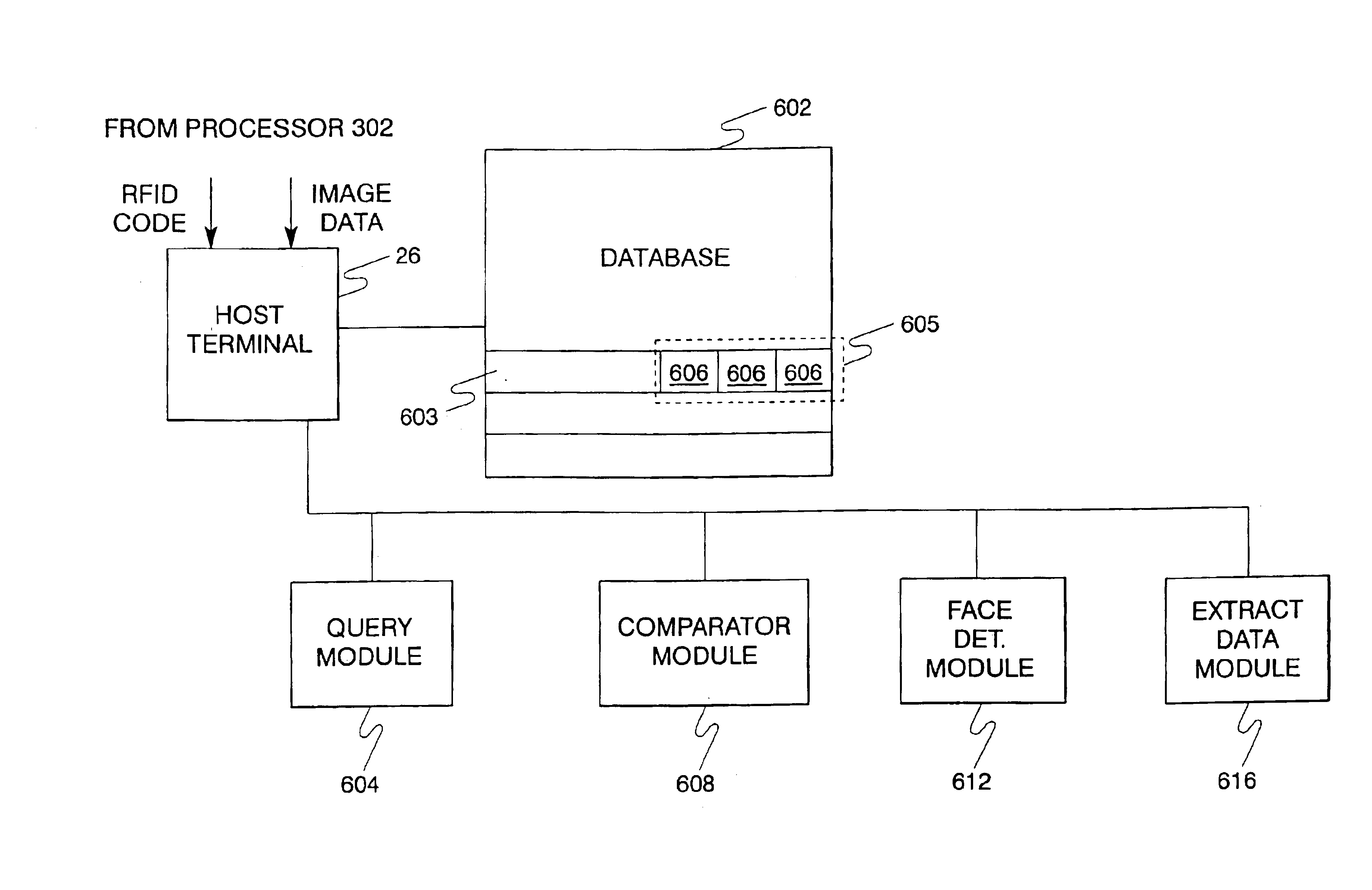
[0035]The present invention provides processes for verifying whether an RFID code transmitted from an RFID tag affixed to an object was read by an RFID reading device of an RFID reading system, or whether another RFID code corresponding to some other object was read. The other object could be located in the same general vicinity as the object whose RFID tag was intended to be read. Without performing a verification process, the RFID reading system would not be able to ascertain whether the RFID code of the intended RFID tag was read. This leads to several obvious disadvantages in different types of applications.

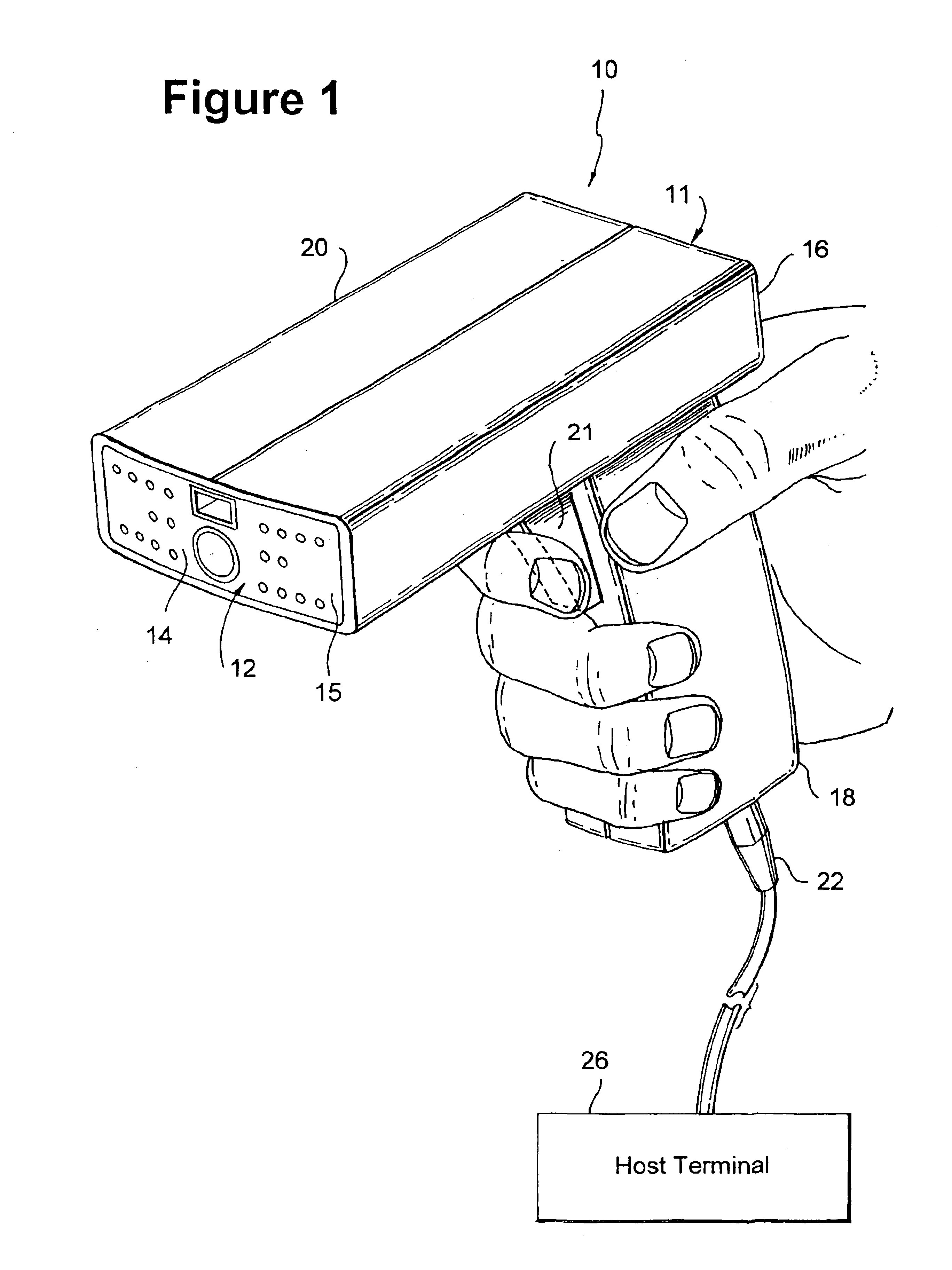
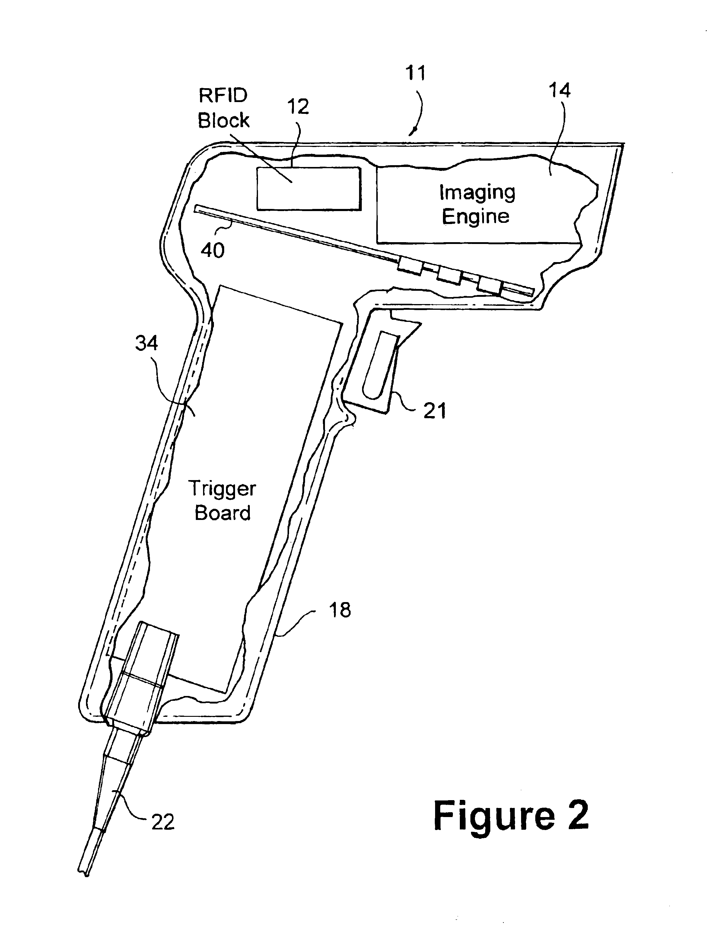
[0036]The present invention also provides an RFID reader and imaging system capable of verifying RFID reads. The system generally includes a processing system having at least one processor capable of executing a set of programmable instructions for performing the various functions of the invention. The system further includes circuitry for interrogating and receiving RFID tag...


PUM


Abstract

A system and method are provided for sensing an image of an object and an optical code associated with the object and generating respective object image data and optical code image data. A database stores a plurality of digital codes and an object image data entry associated with each respective digital code of the plurality of digital codes. A processing unit generates at least one digital code; accesses at least one object image data entry associated with at least one respective stored digital code that substantially matches the respective at least one generated digital code; and compares the object image data with the at least one accessed object image data entry and determines if the comparison results are within a predetermined image recognition certainty threshold.

Description

PRIORITY[0001]This application is a continuation-in-part of U.S. application Ser. No. 10 / 385,941, filed on Mar. 11, 2003, which claims priority to a U.S. Provisional Application filed on Dec. 18, 2002 and assigned U.S. Provisional application Ser. No. 60 / 434,519, the contents of both applications are incorporated herein by reference.BACKGROUND OF THE INVENTION[0002]1. Field of the Invention[0003]This invention relates to verifying read optical indicia, and particularly to verification of optical character recognition of optical code reads using acquired and stored image data.[0004]The invention expands on methodologies and systems used to verify RFID reads as described in U.S. application Ser. No. 10 / 385,941 titled “SYSTEMS AND METHOD FOR VERIFYING RFID READS” and having a common assignee.[0005]2. Description of the Related Art[0006]Radio frequency identification (RFID) is an area of automatic identification in which a transponder, known generally as a tag, attached to an object com...

Claims


Application Information

Patent Timeline
Patent Type & Authority Patents(United States)
IPC IPC(8): G06K7/10G06K7/00G06K19/14G06V30/10G06V30/142
CPCG06K7/0004G06K7/0008G06K7/10386G06K7/10722G06K7/10851G06K9/228G06K9/726G06K19/14G06V30/142G06V30/274G06V30/10G06K17/00G06K7/10
Inventor HE, DUANFENG
Owner SYMBOL TECH LLC
Why Eureka
Try Eureka