High output therapeutic ultrasound transducer

a transducer and ultrasound technology, applied in the field of medical devices and systems, can solve the problems of low tensile strength, ceramic tends to fracture, limited acoustic output of a conventional transducer design, etc., and achieve the effect of excellent ease and simplicity in system wiring

Inactive Publication Date: 2005-07-05
PHARMASONICS
View PDF9 Cites 16 Cited by
  • Summary
  • Abstract
  • Description
  • Claims
  • Application Information

AI Technical Summary

Benefits of technology

[0041]Secondly, being a single continuous element, such a spring connector provides excellent ease and simplicity in system wiring as can be operated as a single electrical contact wire connecting together the inner surfaces of the various transducers.

Problems solved by technology

Unfortunately, the acoustic output from a conventional transducer design is typically limited by the inherent properties of the piezoelectric material which forms the transducer.
Specifically, when operating typical piezoelectric ceramic transducers at high vibrational amplitudes, the ceramic tends to fracture.
This transducer failure is caused by the high tensile stresses within the ceramic material during transducer operation, and the problem is exacerbated by the fact that although piezoelectric ceramic materials tend to have high compressive strengths, they have relatively low tensile strengths.
A further problem common to existing catheter-based ultrasound systems is that they lack the necessary flexibility to negotiate tortuous paths through body lumens.
In such cases, the catheter flexibility is unfortunately influenced both by the number and size of the conductors that are used to interconnect the various transducers.

Method used


Image

  • High output therapeutic ultrasound transducer
  • High output therapeutic ultrasound transducer
  • High output therapeutic ultrasound transducer

Examples


Embodiment Construction

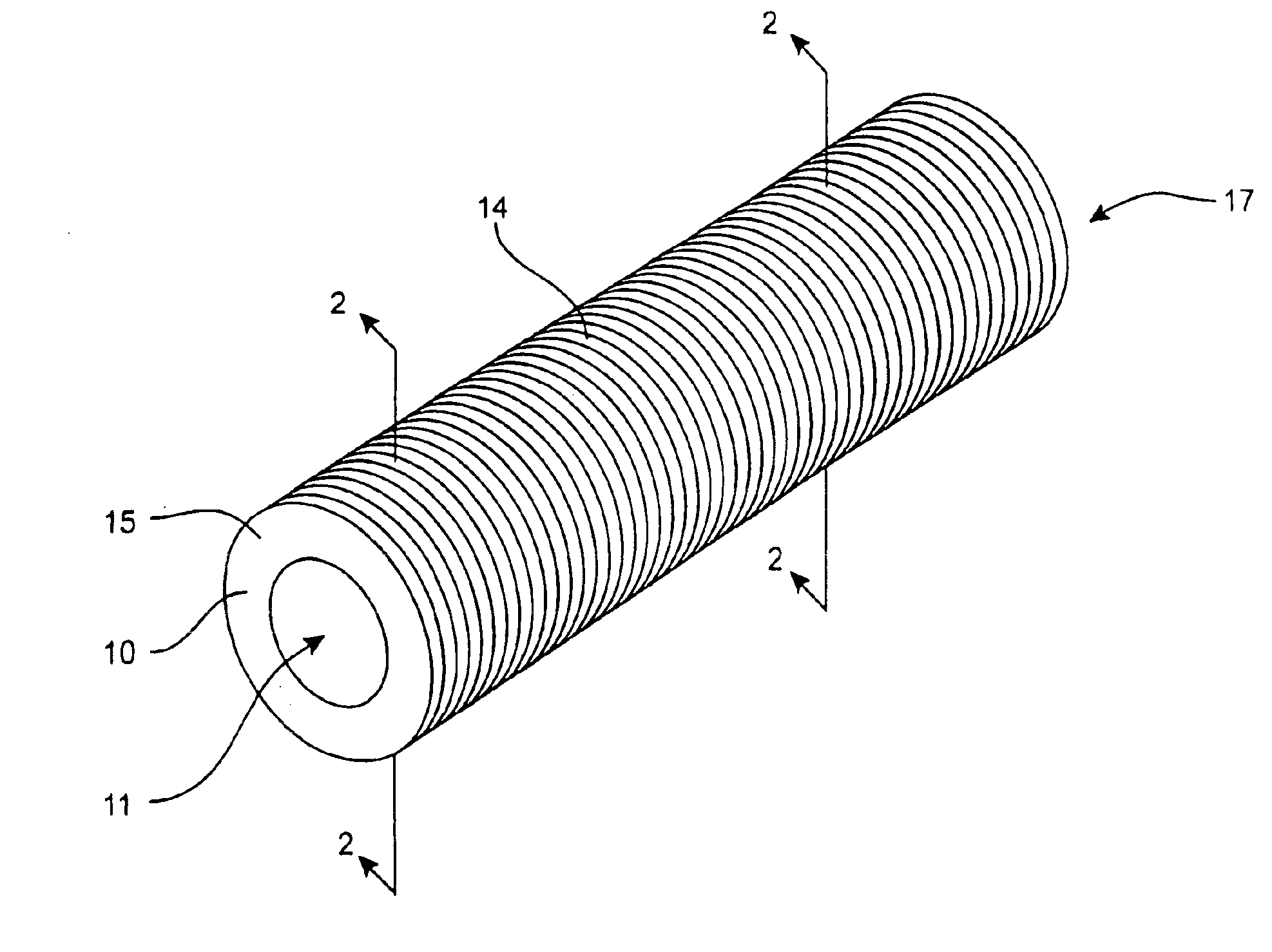
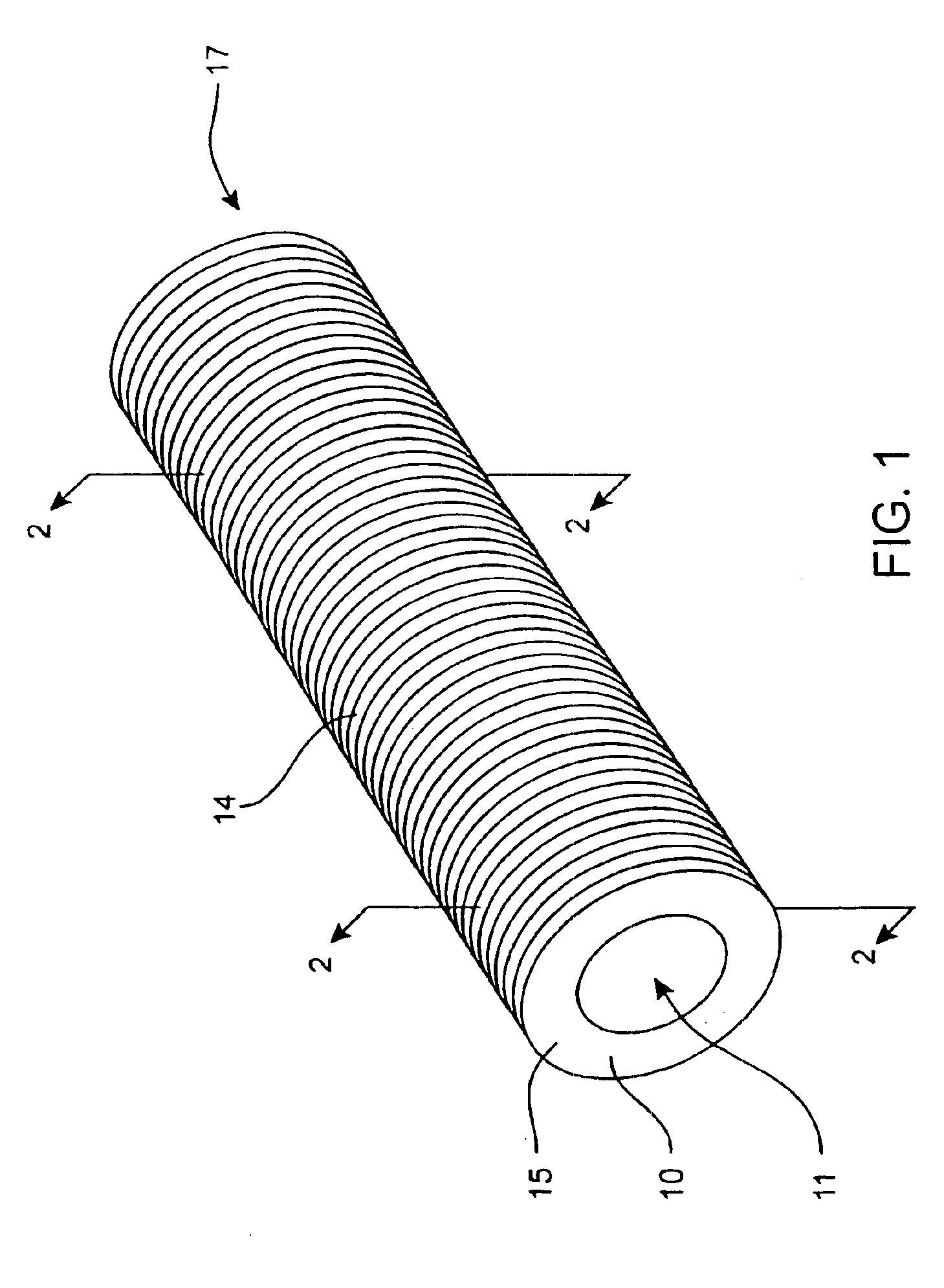
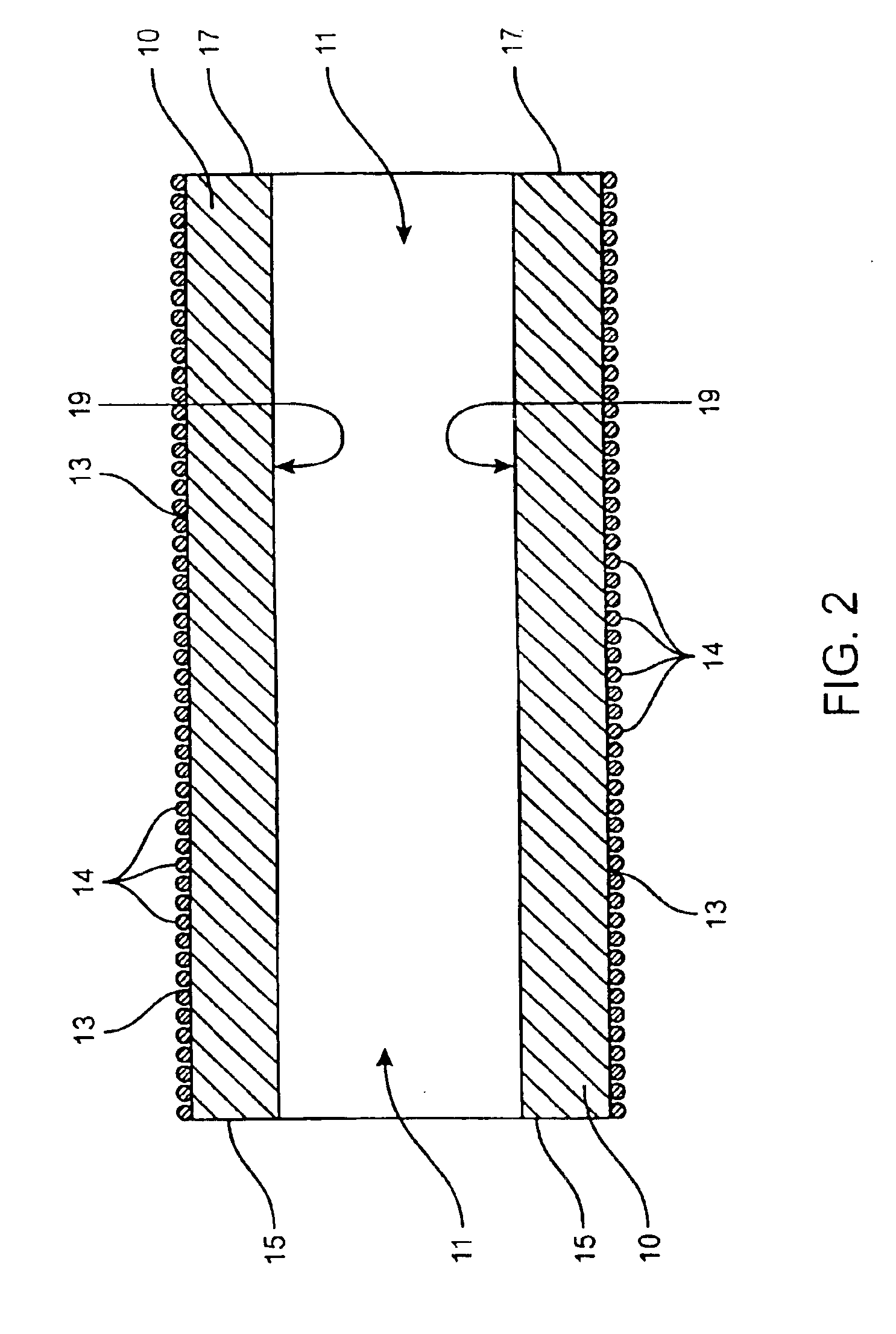
[0063]A problem common to therapeutic ultrasound transducers is that when operating an ultrasound transducer such as a piezoelectric ceramic transducer at a very high output, the transducer will tend to fracture. Accordingly, the therapeutic effectiveness of catheter based ultrasound delivery systems have been somewhat limited since the level of vibrational amplitude of therapeutic ultrasound energy which their transducers are able to emit is limited, especially over prolonged periods of operation.

[0064]Referring to FIGS. 1 and 2, the present invention provides a system for preventing fracture of a ultrasound transducer, (such as a ceramic ultrasound transducer), when the transducer is operated at a high output. In a first aspect, the present invention provides a system for preventing tensile failure in a transducer 10, by way of a wire 14 which is wrapped tightly around transducer 10. As can be seen, transducer 10 is cylindrical shaped, having an optional longitudinally extending c...


PUM


Abstract

A therapeutic ultrasound delivery system, comprises: a catheter body, a plurality of axially spaced-apart hollow cylindrical vibrational transducers disposed along a length of the catheter body, a first spring connector wrapped around the outer surfaces of the vibrational transducers, where the first spring connector exerting an inward pre-stress on the outer surfaces of the vibrational transducers; and a second connector disposed in contact with the inner surfaces of the vibrational transducers. The second connector may comprise a spring coil, particularly a spring coil having multiple deflection points which contact an inner surface of the cylindrical vibrational transducer.

Description

CROSS-REFERENCES TO RELATED APPLICATIONS[0001]The present application is a continuation-in-part of U.S. application Ser. No. 09 / 813,277, filed Mar. 20, 2001 now U.S. Pat. No. 6,508,775, which was a continuation-in-part of U.S. application Ser. No. 09 / 531,027 (U.S. Pat. No. 6,432,068 B1), filed Mar. 20, 2000, the full disclosures which are incorporated herein by reference in its entirety for all purposes.BACKGROUND OF THE INVENTION[0002]The present invention is related to medical devices and systems, particularly therapeutic ultrasound systems.[0003]Percutaneously introduced catheters having ultrasound transducers thereon can be used to deliver localized doses of therapeutic ultrasound energy to various sites within a body. Such systems are ideally suited for treating or preventing pathological conditions such as arterial restenosis due to intimal hyperplasia.[0004]To achieve a high level of therapeutic effectiveness, a high amplitude of ultrasound vibration is required. Unfortunatel...

Claims


Application Information

Patent Timeline
Patent Type & Authority Patents(United States)
IPC IPC(8): A61B17/22
CPCA61B17/2202A61B2017/22021A61B2017/22027
Inventor CORL, PAUL D.MCKENZIE, JOHNKARRATT, JOSEPHHULME, GARY
Owner PHARMASONICS
Why Eureka
Try Eureka