Electromagnetic switch for a starter

a technology of electric switch and starter, which is applied in the direction of engine starters, machines/engines, relays, etc., can solve the problems of reducing the radial space of the coil housing, limiting the radial size of the coil accommodated in the coil housing, and significantly taking a long time to accomplish the work of connecting the lead lines of the coil. , to achieve the effect of facilitating and surely bringing and extending the radial space of the solenoid cas

Inactive Publication Date: 2005-07-05
DENSO CORP +1
View PDF13 Cites 7 Cited by
  • Summary
  • Abstract
  • Description
  • Claims
  • Application Information

AI Technical Summary

Benefits of technology

[0005]In view of the above-described problems, the present invention has an object to provide an electromagnetic switch for a starter which is capable of easily and surely bringin

Problems solved by technology

It significantly takes a long time to accomplish the work for connecting the lead lines of the coil.
This clearance brings a disadvantage to the above-described conventional magnetic switch in that an available radial space for the coil housing is inevitably reduced due

Method used


Image

  • Electromagnetic switch for a starter
  • Electromagnetic switch for a starter
  • Electromagnetic switch for a starter

Examples


Embodiment Construction

[0029]Preferred embodiments of the present invention will be explained hereinafter with reference to attached drawings.

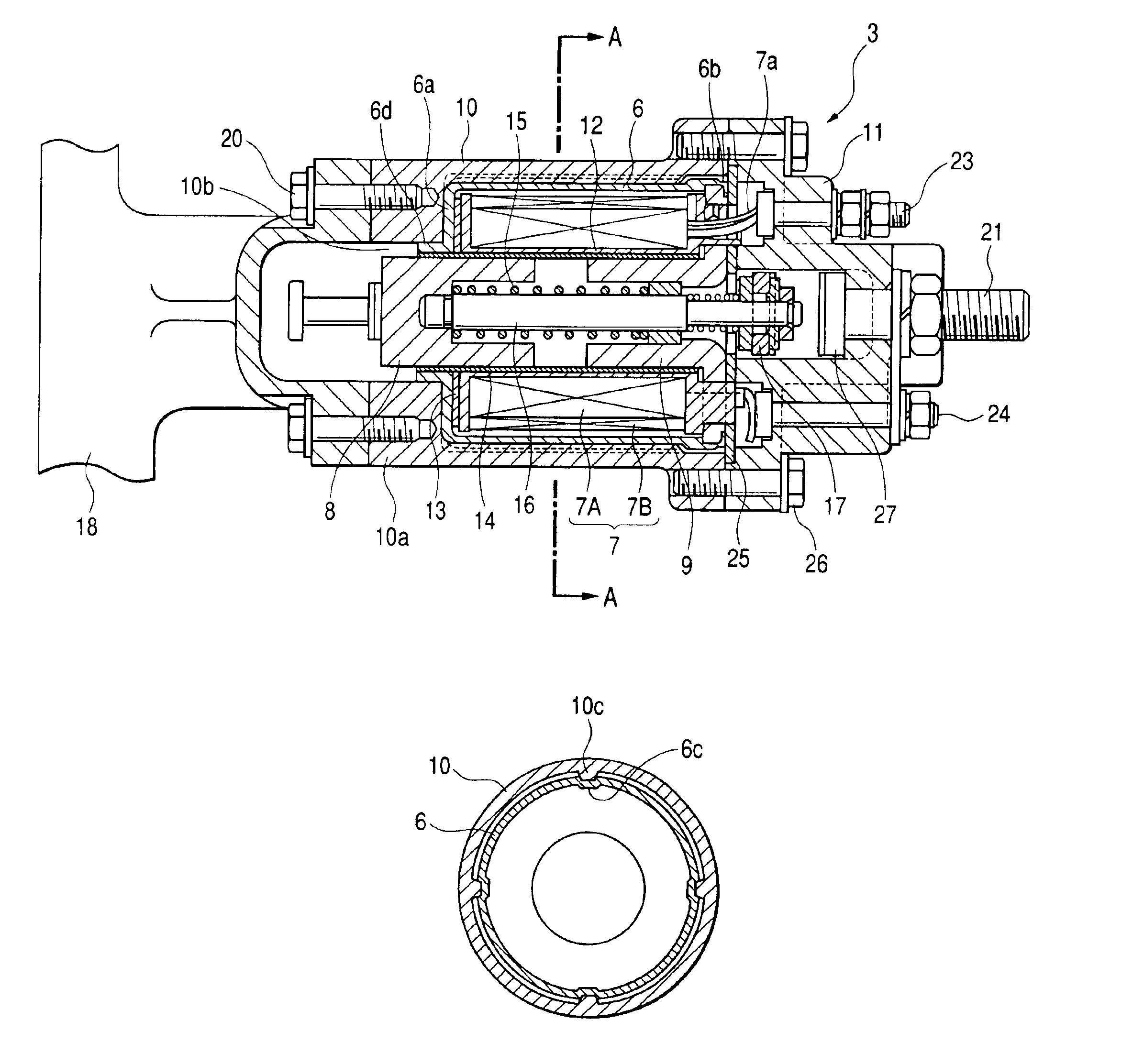
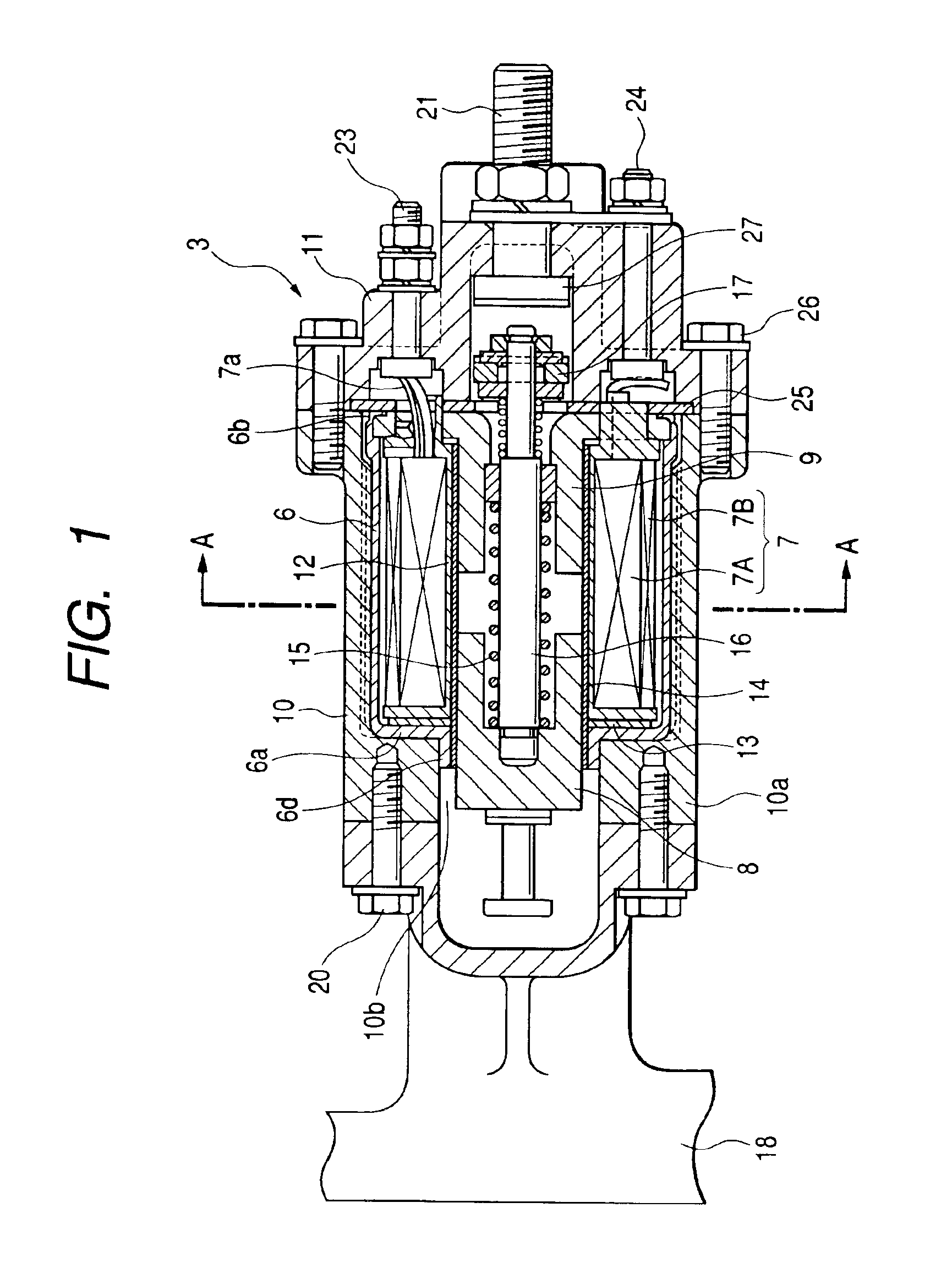
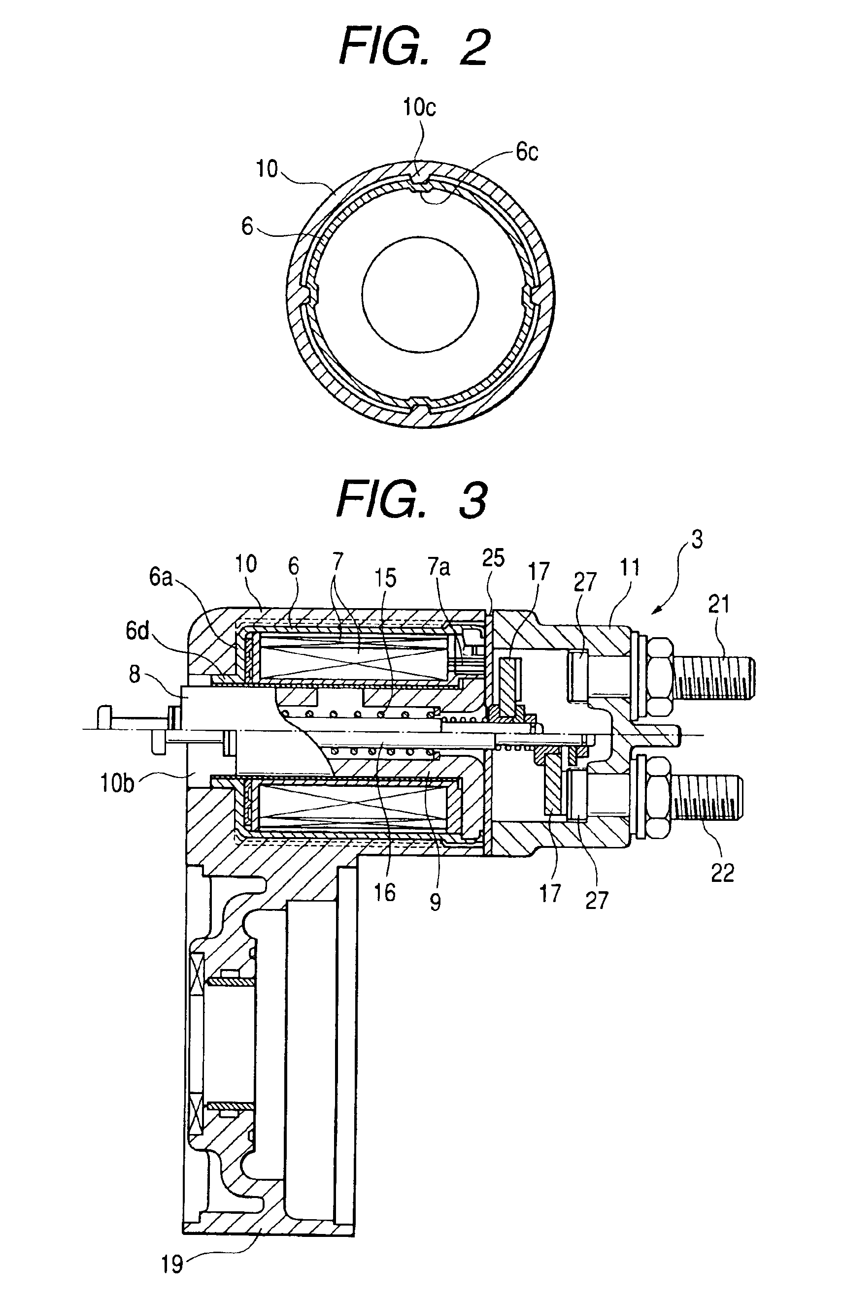
[0030]FIG. 1 is a cross-sectional view showing an electromagnetic switch 3 taken along a horizontal plane. FIG. 3 is a cross-sectional view showing the electromagnetic switch 3 taken along a vertical plane.

[0031]A starter 1 according to this embodiment, as shown in FIG. 4, includes a motor 2 which produces a rotational force required to start an engine. An electromagnetic switch 3 controls electric power supply to the motor 2. A pinion gear 5 selectively engages with a ring gear 4 of the engine to transmit the rotational force of the motor 2 to the ring gear 4.

[0032]The motor 2 is a well-known DC (i.e., direct-current) motor. When an ignition key (not shown) is turned on, the electromagnetic switch 3 closes a later-described motor contact incorporated therein. When the motor contact is closed, electric power is supplied from a vehicle battery (not shown) to an armat...


PUM


Abstract

An electromagnetic switch has at least one pair of projection and groove engageable with each other and extending in an axial direction on an outer cylindrical surface of a solenoid casing and on an inner cylindrical surface of a switch casing. Engagement of the projection and the groove guides the solenoid casing shifting in the axial direction when inserted inside the switch casing.

Description

BACKGROUND OF THE INVENTION[0001]This invention relates to an electromagnetic switch for a starter equipped with a switch casing for accommodating a solenoid casing which forms part of a magnetic circuit.[0002]Japanese Patent No. 2973577 discloses a conventional magnet switch for a starter which includes a coil housing (i.e., a solenoid casing) coupled around an outer cylindrical surface of a coil and a starter casing (i.e., a switch casing) having an inside space for accommodating the coil housing. This magnet switch has a plurality of protrusions provided on an outer cylindrical surface of the coil housing or on an inner cylindrical surface of the starter casing. The coil housing is press-fitted into the starter casing, with the protrusions intervening between the coil housing and the starter casing.[0003]However, according to the arrangement of the above-described conventional magnet switch, the circumferential position of the coil housing is arbitrarily changed with respect to t...

Claims


Application Information

Patent Timeline
IPC IPC(8): H01H51/00H01H51/06F02N11/00H01H50/04
CPCH01H51/065F02N15/006F02N15/067H02K7/14F02N11/087
Inventor KAJINO, SADAYOSHIHASEGAWA, YOUICHIAOKI, SYUICHIOMIYAMA, HIROYASU
Owner DENSO CORP
Why Eureka
Try Eureka