Wide band antenna

a wideband antenna and wideband technology, applied in the direction of antennas, antenna details, basic electric elements, etc., can solve the problems of sharp operation bandwidth of patch antennas and unsuitable pan systems that require a wider operational bandwidth, and achieve the effect of sufficient gain and easy impedance matching

Inactive Publication Date: 2005-07-05
TESSERA ADVANCED TECH
View PDF9 Cites 13 Cited by
  • Summary
  • Abstract
  • Description
  • Claims
  • Application Information

AI Technical Summary

Benefits of technology

[0013]According to the wideband antenna as mentioned above, the substance having the conductivity of about 0.1 through 10 is interposed between the reference conductor and the radiation conductor, and thereby the antenna appropriately leaks signals into the substance between the reference conductor and the radiation conductor, which makes it possible to achieve a wideband antenna with a sufficient gain and lowered standing wave ratio.
[0015]According to the above thin-type wideband antenna, the magnetic substance whose relative permeability is more than 1 through about 8 in the operational radio frequency is interposed between the reference conductor and the radiation conductor, which makes it possible to achieve a thin-type wideband antenna with a sufficient gain.
[0016]And, the impedance matching can easily be achieved by connecting the matching capacitor in series or in parallel, or in series and parallel to the feeding point.

Problems solved by technology

However, the patch antenna has a sharp operational bandwidth.
Therefore, it is not suitable for the PAN system that requires a wider operational bandwidth.

Method used


Image

  • Wide band antenna
  • Wide band antenna
  • Wide band antenna

Examples


first embodiment

[First Embodiment]

[0038]The wideband antenna of the first embodiment is created with attention to the conductivity a of a substance being interposed between a reference conductor and a radiation conductor. The first embodiment uses the substance whose conductivity σ is within a specific range of comparably large conductivities. The antenna appropriately leaks signals into the substance between the reference conductor and the radiation conductor to bear a loss, and thereby reduces reflected waves to lower the standing wave ratio, and to widen the operational bandwidth.

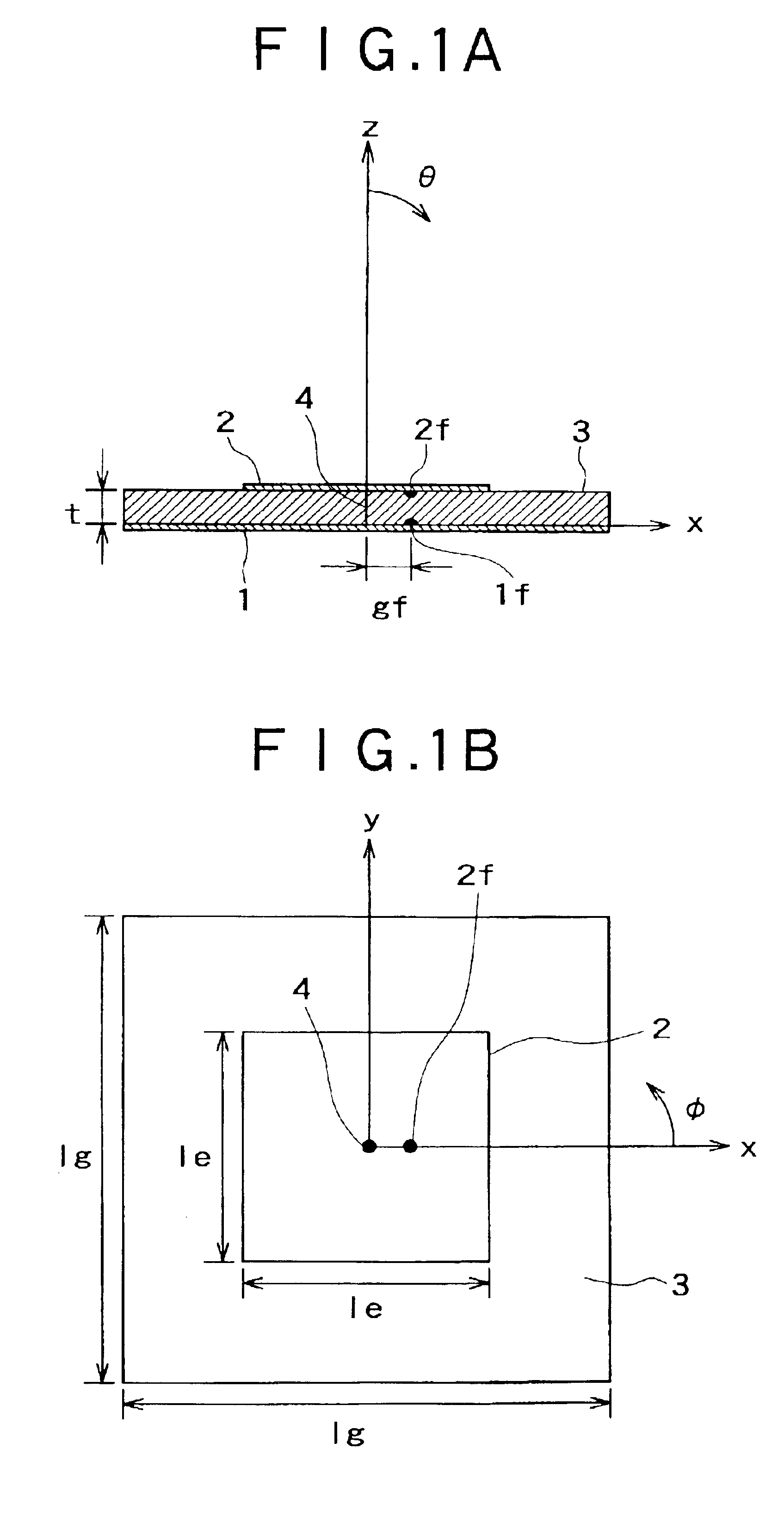
[0039]The wideband antenna of this invention is applicable to various antennas that are formed with a substance having a specific conductivity interposed between the reference conductor and the radiation conductor. Hereunder, an example will be explained, in which the invention is applied to the so-called patch antenna.

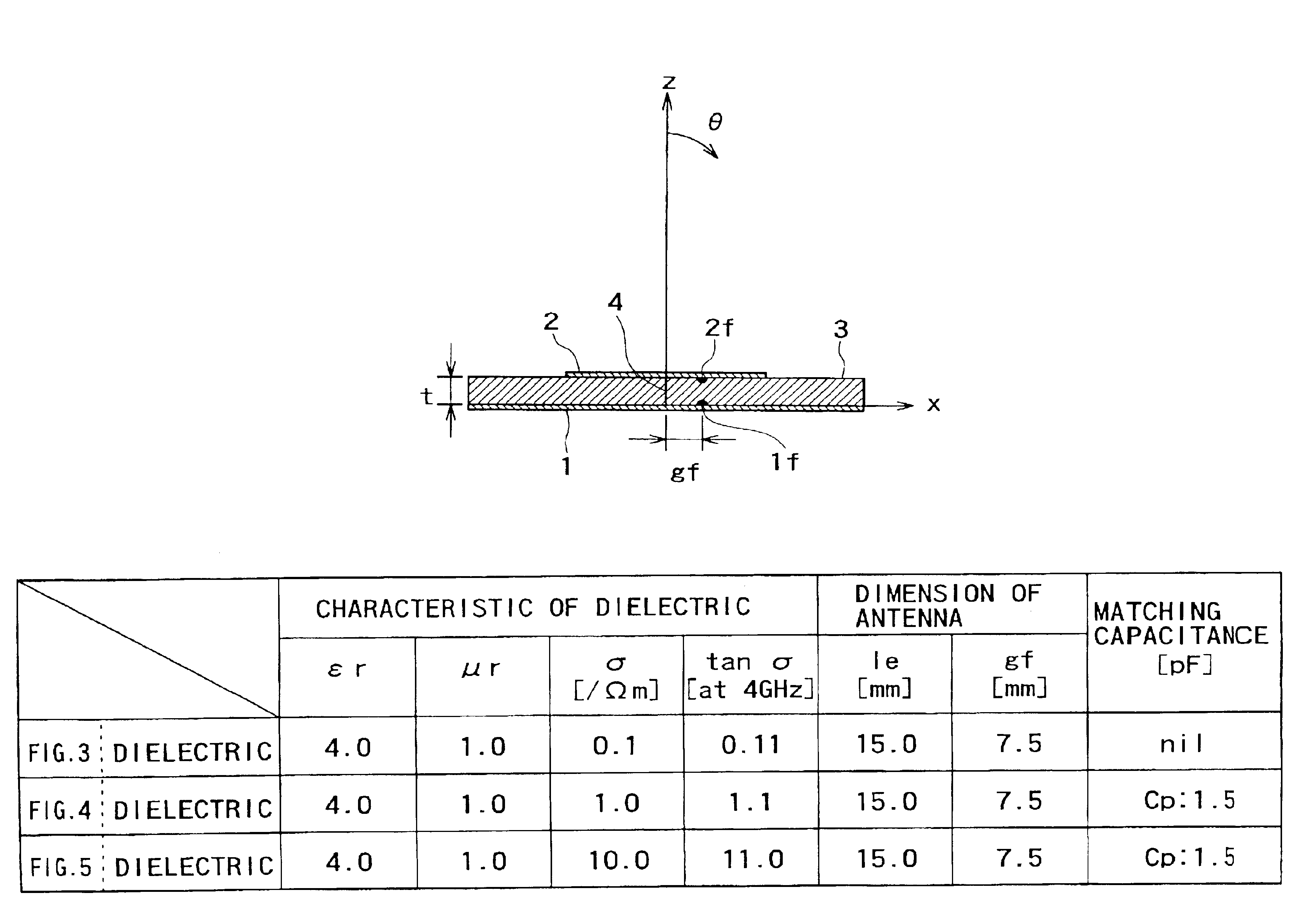
[0040]FIG. 1 is a chart that explains a construction of the wideband antenna of the first embodiment. ...

second embodiment

[Second Embodiment]

[0057]The wideband antenna of the second embodiment is created with attention to the relative permeability μr of a substance being interposed between the reference conductor and the radiation conductor. The second embodiment uses a magnetic substance as the interposition, of which relative permeability μr is within a specific range, thereby further widening the operational bandwidth of the wideband antenna.

[0058]FIG. 6 is a chart explaining the construction of a thin-type wideband antenna relating to the second embodiment, in which FIG. 6A is a side view of the thin-type wideband antenna of this embodiment, and FIG. 6B is a top view explaining the same. As shown in FIG. 6, the thin-type wideband antenna of the second embodiment is made up in the same manner as the wideband antenna of the first embodiment.

[0059]However, the wideband antenna of the second embodiment has been created from a novel idea of using a magnetic substance instead of a dielectric substance as...

third embodiment

[Third Embodiment]

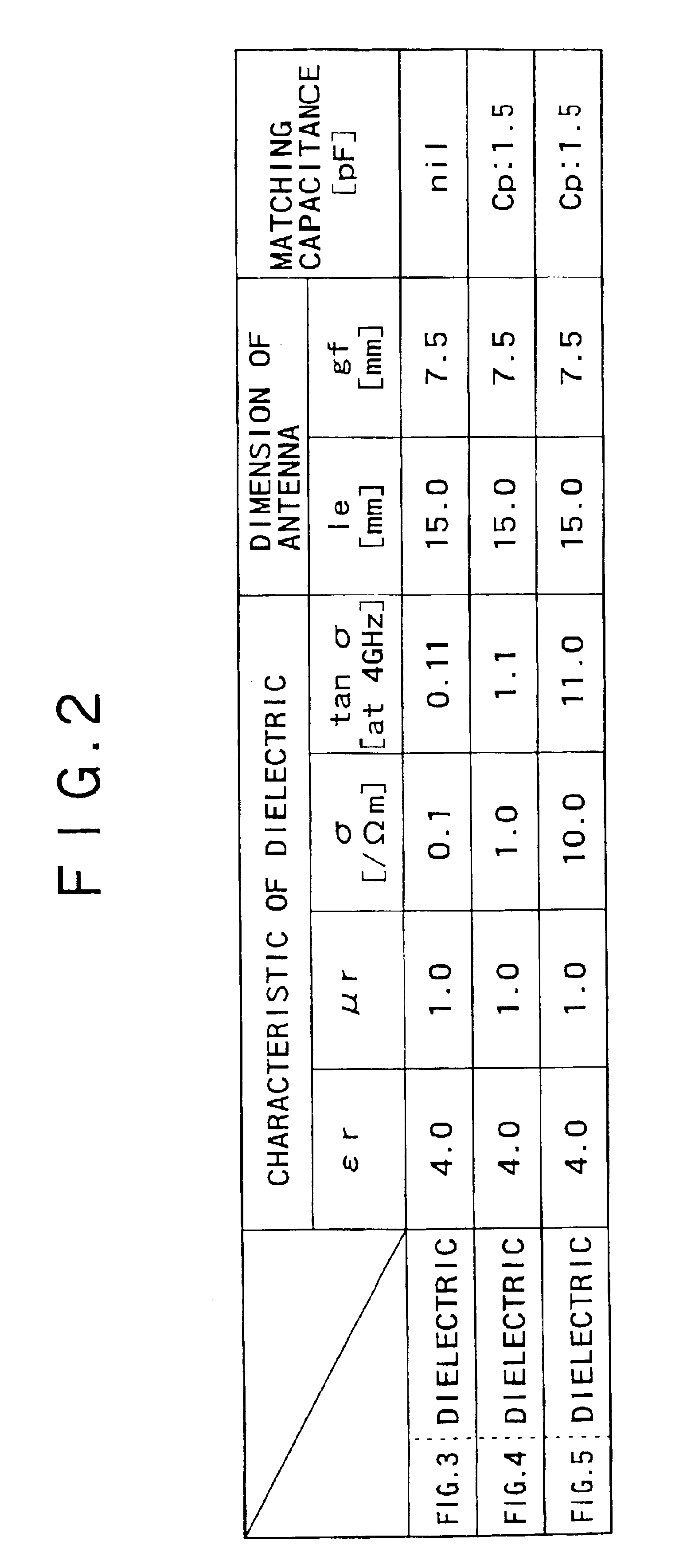
[0078]In the first embodiment, as the interposition 3 interposed between the reference conductor 1 and the radiation conductor 2, a dielectric material having the conductivity σ of about 0.1 [ / Ωm] through 10.0 [ / Ωm] is used. However, it is conceivable to use a magnetic substance as the interposition, as described in the second embodiment.

[0079]Now, a magnetic substance is used as the interposition also in the third embodiment; however, the magnetic substance interposed here is specified not only by the relative permeability μr, which is the case with the second embodiment, but also by the conductivity σ that the magnetic substance interposed between a reference conductor and a radiation conductor possesses.

[0080]That is, the wideband antenna of the third embodiment uses a magnetic substance as the interposition between a reference conductor and a radiation conductor, of which conductivity σ belongs to a specific range of comparably large conductivities. Thereby, th...


PUM


Abstract

Disclosed is a wideband antenna with a lowered standing wave ratio. The wideband antenna interposes a substance whose conductivity is about 0.1 through 10.0 as an interposition between a conductive plate and a radiation conductor; and thereby, the antenna reduces reflections of signals, and achieves a wider bandwidth as well as a sufficient gain with a lowered standing wave ratio. Also, the invention realizes a thin-type wideband antenna with a wider bandwidth and a sufficient gain, by interposing a magnetic substance whose relative permeability is more than 1 through about 8 as the interposition between the conductive plate and the radiation conductor.

Description

BACKGROUND OF THE INVENTION[0001]1. Field of the Invention[0002]The present invention relates to a thin-type wideband antenna used in a communication system that requires an ultra wideband and miniature antenna, such as a broadband Personal Area Network (PAN) using the Ultra Wide-Band (UWB) technique, for example.[0003]2. Description of Related Art[0004]To implement the broadband PAN using the UWB technique an ultra wideband and miniature antenna are utilized. The so-called patch antenna (thin-type antenna) answers the requirement especially for the thin-type. The patch antenna is constructed of an insulating substance interposed between a radiation conductor and a reference conductor which are in facing relationship with respect to each other.[0005]The shape of the radiation conductor is not especially restricted, however in general, a rectangular shape or circular is used. Generally, the thickness of the insulating substance interposed between the radiation conductor and the refer...

Claims


Application Information

Patent Timeline
Patent Type & Authority Patents(United States)
IPC IPC(8): H01Q9/04H01Q1/38H01Q13/08
CPCH01Q1/38H01Q9/0421
Inventor KURODA, SHINICHIYAMAURA, TOMOYA
Owner TESSERA ADVANCED TECH
Why Eureka
Try Eureka