Pipe structure, alignment apparatus, electron beam lithography apparatus, exposure apparatus, exposure apparatus maintenance method, semiconductor device manufacturing method, and semiconductor manufacturing factory

a technology of alignment apparatus and exposure apparatus, which is applied in the direction of photomechanical apparatus, soldering apparatus, instruments, etc., can solve the problems of metal fatigue, adversely affecting alignment precision, and high load resistance of movement, so as to prevent the influence of degassing and high flexibility and durability

Inactive Publication Date: 2005-07-05
CANON KK
View PDF15 Cites 15 Cited by
  • Summary
  • Abstract
  • Description
  • Claims
  • Application Information

AI Technical Summary

Benefits of technology

[0008]The present invention has been made to overcome the conventional drawbacks, and has as its object to provide a pipe structure which is higher in flexibility and durability than a conventional metal pipe and is connected to an alignment apparatus arranged in a vacuum chamber. It is another object of the present invention to provide a pipe structure which also prevents the influence of degassing from an electrical wire.

Problems solved by technology

(i) Because of low flexibility (high flexural rigidity), the load resistance of movement is high.
In other words, a force in deforming the pipes acts as a disturbance factor to the stage 503, which adversely influence the alignment precision.
(ii) Repetitive deformation of the metal pipes 6 readily causes metal fatigue and decreases the durability.
In particular, the alignment precision of the high-precision stage 503 is adversely influenced by the nonlinear piping force of even a pipe made of a flexible resin material.
For this reason, the low flexibility of the metal pipe poses a serious problem, and demands are arising for a flexible pipe usable in a vacuum chamber.
In general, a resin material exhibits a larger amount of degassing or gas permeation than a metal pipe, so a resin pipe is difficult to directly use in a medium to high vacuum atmosphere.

Method used


Image

  • Pipe structure, alignment apparatus, electron beam lithography apparatus, exposure apparatus, exposure apparatus maintenance method, semiconductor device manufacturing method, and semiconductor manufacturing factory
  • Pipe structure, alignment apparatus, electron beam lithography apparatus, exposure apparatus, exposure apparatus maintenance method, semiconductor device manufacturing method, and semiconductor manufacturing factory
  • Pipe structure, alignment apparatus, electron beam lithography apparatus, exposure apparatus, exposure apparatus maintenance method, semiconductor device manufacturing method, and semiconductor manufacturing factory

Examples


first embodiment

[First Embodiment]

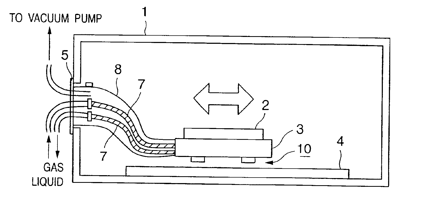
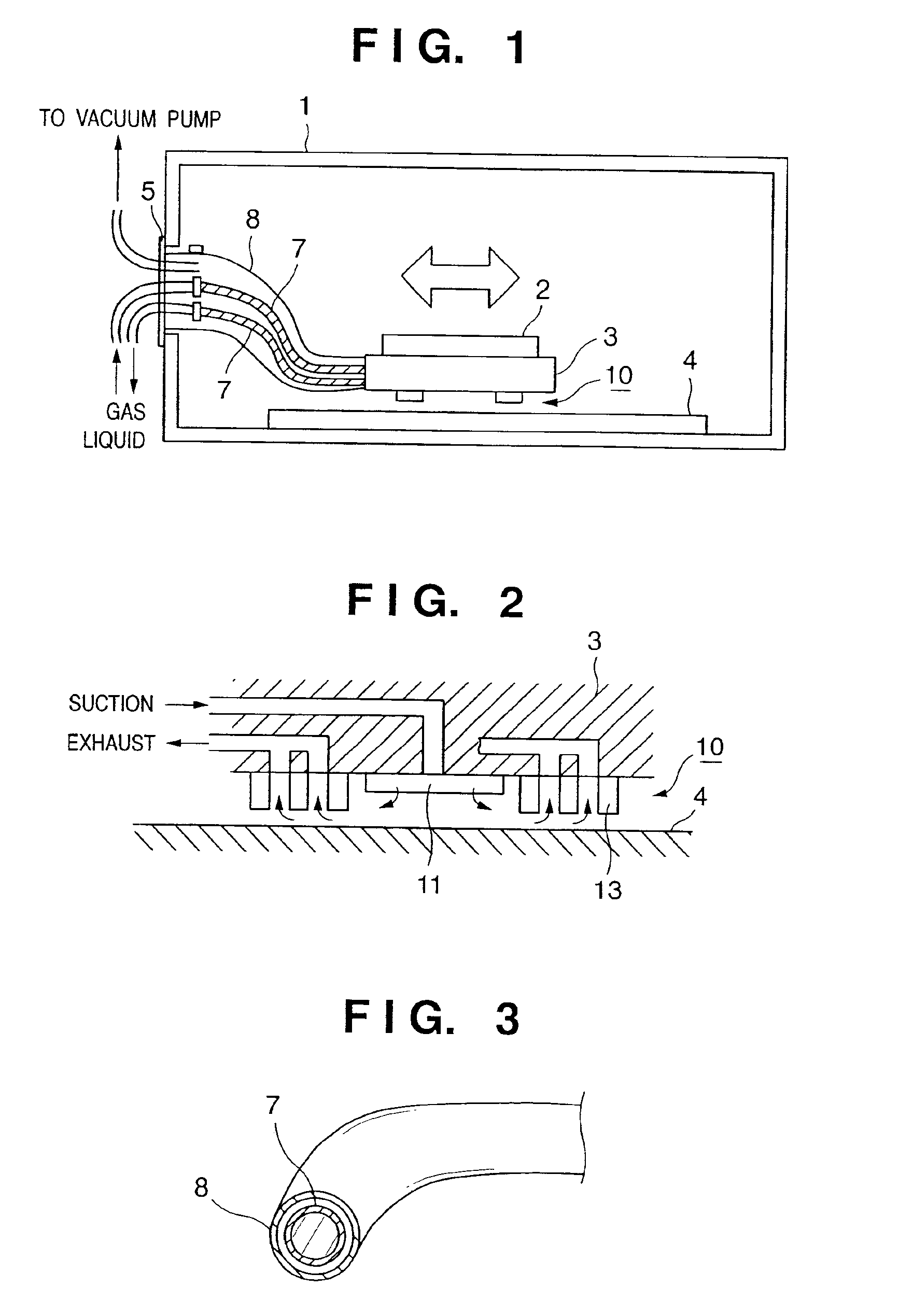
[0033]FIG. 1 is a schematic view showing the main part of an alignment apparatus arranged in a vacuum chamber according to the first embodiment of the present invention, and shows the present invention best.

[0034]In FIG. 1, reference numeral 1 denotes a vacuum chamber whose interior is controlled to a vacuum atmosphere. The vacuum chamber 1 has a vacuum pump (not shown). Gas in the vacuum chamber 1 is discharged by the vacuum pump, and the interior of the vacuum chamber is controlled to a medium to high vacuum atmosphere.

[0035]Reference numeral 3 denotes a stage which is movable on a surface plate 4 having a reference surface by a driving mechanism (not shown). An object 2 to be aligned is held by a chuck (not shown) on the stage 3.

[0036]The stage 3 is supported above the surface plate 4 in a non-contact manner by a bearing mechanism 10.

[0037]The bearing mechanism 10 will be explained with reference to FIG. 2. In FIG. 2, the same reference numerals as those in FIG....

second embodiment

[Second Embodiment]

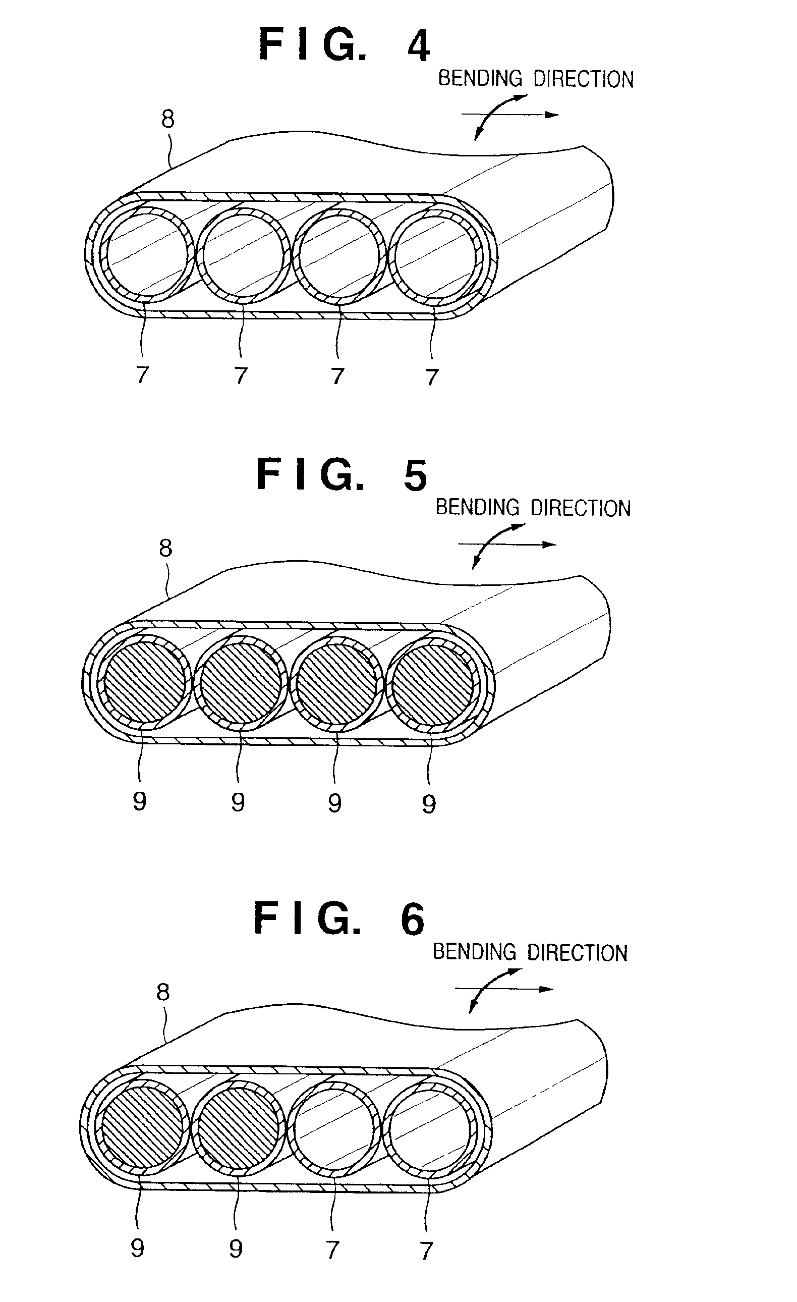
[0053]FIG. 5 shows an example when a vacuum sealing structure according to the second embodiment of the present invention is applied to an electrical wire. In general, an electrical wire also often uses a fluoroplastic-coated wire in order to reduce degassing from the coated portion of the wire. However, the fluoroplastic coating is poorer in flexibility than general coating, and is not appropriate for connection to a movable member (stage), similar to a pipe. To form electrical wires 9 almost free from degassing while maintaining prescribed flexibility, the electrical wires 9 are covered with a fluoroplastic outer pipe 8 having a small thickness (e.g., several tens of μm), and the interior of the outer pipe 8 is kept in a low vacuum by a pump. Thus, even if the electrical wire 9 itself is formed from a flexible wire such as a vinyl-coated wire regardless of degassing, degassing does not influence a high vacuum atmosphere. This is because the pressure difference i...


PUM

PropertyMeasurementUnit
thicknessaaaaaaaaaa
pressureaaaaaaaaaa
pressureaaaaaaaaaa

Abstract

A pipe structure includes a double pipe having a resin inner pipe and a resin outer pipe covering an outside of the inner pipe, and a discharge mechanism for discharging fluid in a space between the inner pipe and the outer pipe. The double pipe is used in a vacuum chamber having a vacuum atmosphere.

Description

FIELD OF THE INVENTION[0001]The present invention relates to a pipe structure, an alignment apparatus, an electron beam lithography apparatus, an exposure apparatus, an exposure apparatus maintenance method, a semiconductor device manufacturing method, and a semiconductor manufacturing factory capable of maintaining a vacuum atmosphere having a medium to high vacuum degree at a high precision by preventing any adverse effect such as a decrease in vacuum degree in a vacuum chamber caused by degassing, gas permeation, or the like, from a pipe structure connected to externally supplied fluid such as gas (or liquid) in order to drive the alignment apparatus arranged in the evacuated vacuum chamber.BACKGROUND OF THE INVENTION[0002]A metal pipe has conventionally been used to suppress a decrease in vacuum degree in a vacuum chamber by degassing or gas permeation from a pipe when the interior and exterior of the vacuum chamber evacuated to a medium to high vacuum atmosphere are connected v...

Claims


Application Information

Patent Timeline
Patent Type & Authority Patents(United States)
IPC IPC(8): F16L9/19F16L9/18G03F7/20H01L21/00H01J37/20G12B5/00H01J37/18H01J37/305H01L21/02H01L21/027
CPCB82Y10/00B82Y40/00F16L9/18F16L9/19G03F7/70716G03F7/70875H01J37/20H01J37/3174H01L21/67017G03F7/70991Y10T29/41H01L21/67155H01L21/67242
Inventor EMOTO, KEIJI
Owner CANON KK
Why Eureka
Try Eureka