Method of manufacturing variable vane seal and washer materials

a technology of variable vane and washer, which is applied in the direction of machines/engines, liquid fuel engines, soldering apparatus, etc., can solve the problems of air leakage pathways, failure of fibers within the bearing assembly, and eventual failure of the variable vane assembly, and achieve low friction coefficient, improve the service life of the stator vane assembly, and achieve performance characteristics. desirable

Inactive Publication Date: 2005-07-12
GENERAL ELECTRIC CO
View PDF27 Cites 7 Cited by
  • Summary
  • Abstract
  • Description
  • Claims
  • Application Information

AI Technical Summary

Benefits of technology

[0010]The seal prevents the stator vane from contacting the stator casing and prevents air flow from exiting the opening. The washer prevents contact between a spacer and the casing and also prevents air flow from exiting the opening. The bearing assembly thus provides two barriers to air flow escaping through the opening in the stator casing.
[0011]The seal and washer are fabricated from a combination of materials, such as Teflon fibers and glass fibers impregnated with a polyimide resin, that have desirable performance characteristics and that provide a low coefficient of friction. In addition, the bearing assembly materials significantly improve the service life of the stator vane assembly and reduce air leakage through the opening in the stator casing. Further, the bearing assembly provides an efficiency improvement in the turbine engine while reducing overhaul costs caused by metal on metal contact between the stator casing, the stator vane, and the spacer.

Problems solved by technology

Such variable vane assemblies have possible air leakage pathways through the openings in the casing.
Also, the high velocity and high temperature air causes oxidation and erosion of the bearing assemblies, which may lead to failure of fibers within the bearing assembly, and eventual failure of the variable vane assembly.
Once the bearing assembly fails, an increase in leakage through the opening occurs, which results in a performance loss.
In addition, failure of the bearing assembly allows contact between the stator vane and the casing, which causes wear and increases overhaul costs of the engine.

Method used


Image

  • Method of manufacturing variable vane seal and washer materials
  • Method of manufacturing variable vane seal and washer materials
  • Method of manufacturing variable vane seal and washer materials

Examples


Embodiment Construction

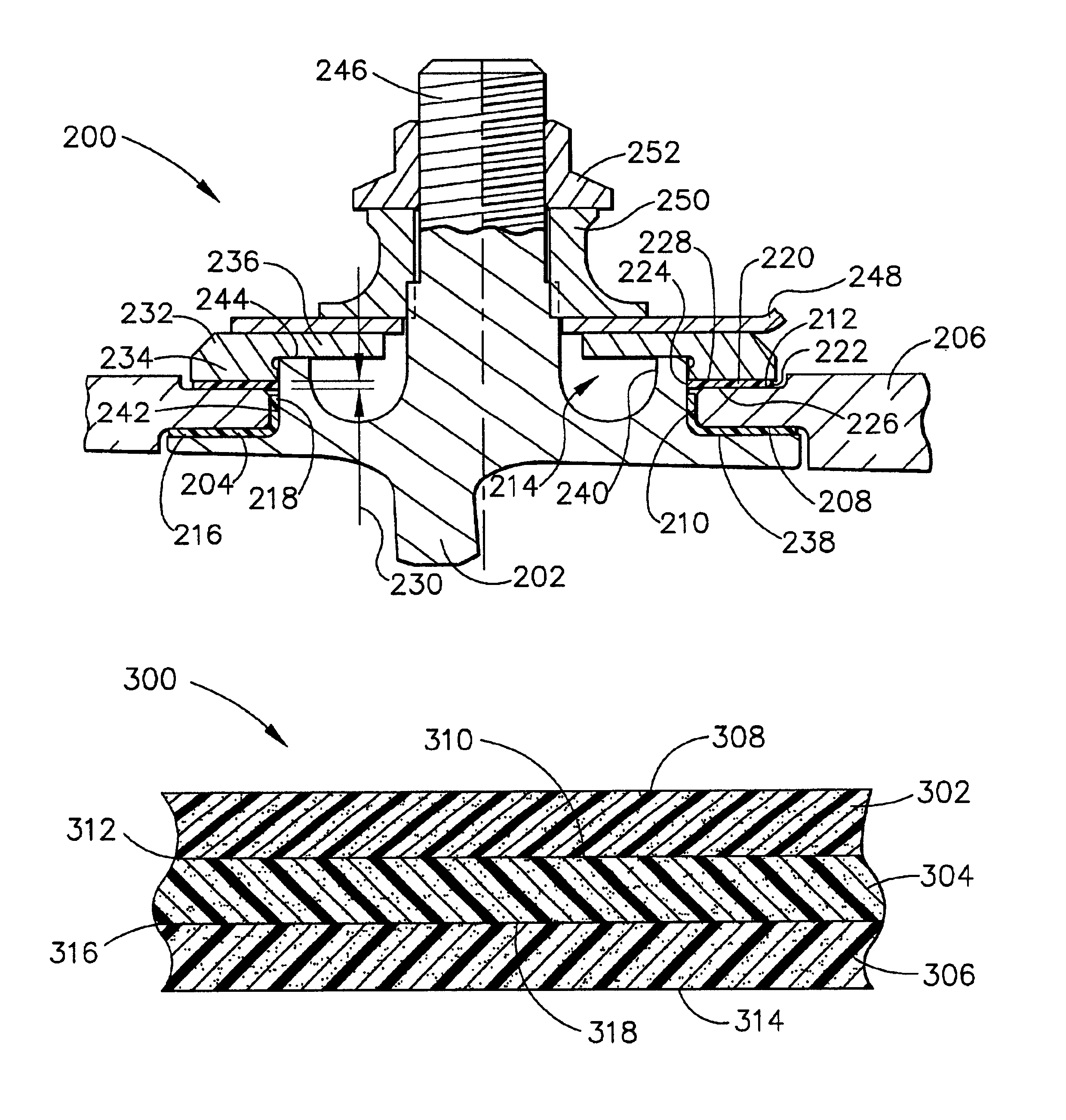
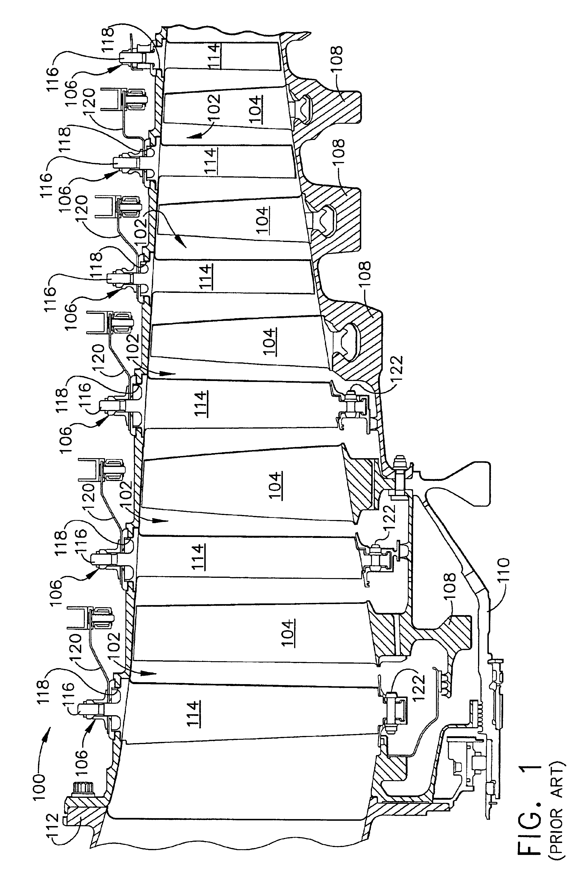
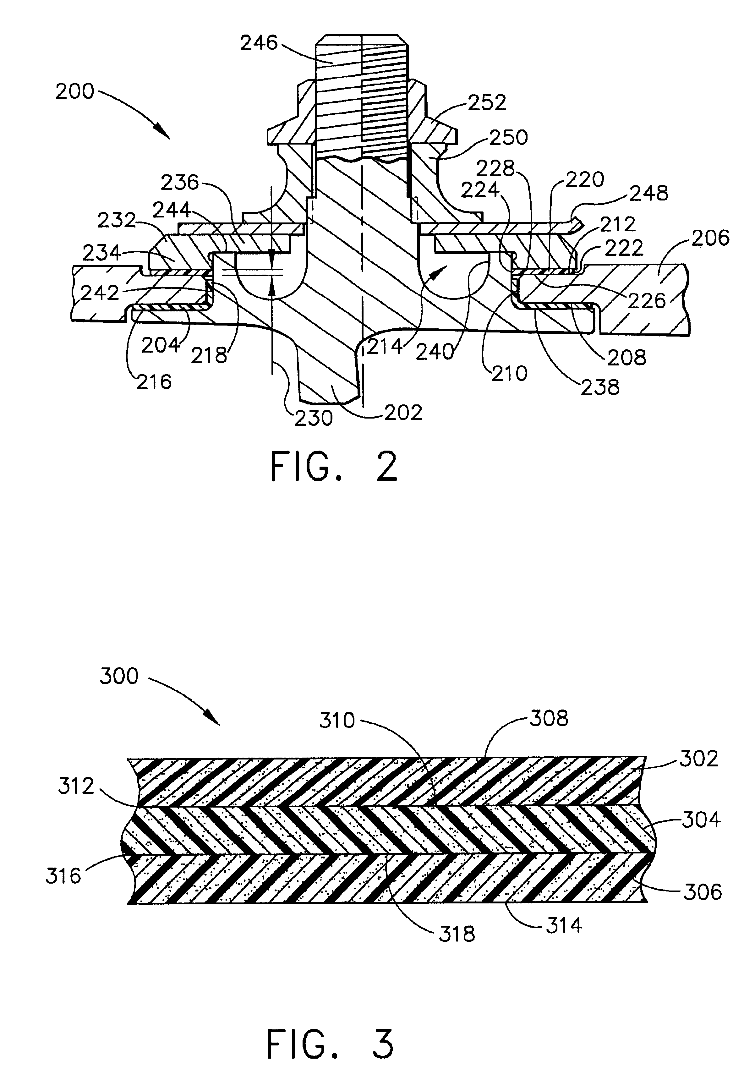
[0015]FIG. 1 is a schematic view of a section of a high pressure compressor 100 for a turbine engine (not shown). Compressor 100 includes a plurality of stages 102, and each stage 102 includes a row of rotor blades 104 and a row of variable stator vane assemblies 106. Rotor blades 104 are typically supported by rotor disks 108, and are connected to a rotor shaft 110. Rotor shaft 110 is a high pressure shaft that is also connected to a high pressure turbine (not shown). Rotor shaft 110 is surrounded by a stator casing 112 that supports variable stator vane assemblies 106.

[0016]Each variable stator vane assembly 106 includes a variable vane 114 and a vane stem 116. Vane stem 116 protrudes through an opening 118 in casing 112. Variable vane assemblies 106 further include a lever arm 120 extending from variable vane 114 that is utilized to rotate variable vanes 114. The orientation of vanes 114 relative to the flow path through compressor 100 controls air flow therethrough. Some variabl...


PUM

PropertyMeasurementUnit
concentrationaaaaaaaaaa
energyaaaaaaaaaa
pressureaaaaaaaaaa

Abstract

A multi-layer seal and washer that provide a seal between a vane stem and a casing in a turbine engine are disclosed. The seal and washer are fabricated from materials such as Teflon fibers and glass fibers and are impregnated with a polyimide resin. The seal and washer are durable and have a low coefficient of friction.

Description

[0001]This application is a divisional of U.S. application Ser. No. 09 / 239,639, filed Jan. 29, 1999, now U.S. Pat. No. 6,264,369.BACKGROUND OF THE INVENTION[0002]This invention relates generally to bearing assemblies and, more particularly, to bearing assembly materials.[0003]Gas turbine engines generally include a high pressure compressor, a combustor, and a high pressure turbine. Compressed air flows through the engine while fuel is mixed with the compressed air and ignited to form a high energy gas steam in the high pressure compressor and combustor, respectively. The high pressure compressor, combustor, and high pressure turbine are sometimes collectively referred to as a core engine. Such gas turbine engines also may include a low pressure compressor for supplying compressed air, for further compression, to the high pressure compressor, and a fan for supplying air to the low pressure compressor.[0004]The high pressure compressor typically includes a rotor surrounded by a casing...

Claims


Application Information

Patent Timeline
Patent Type & Authority Patents(United States)
IPC IPC(8): F04D29/02F04D29/00F01D17/16F01D17/00F04D29/08F16C33/18F16J15/16
CPCF01D17/162F04D29/023F04D29/083Y10S384/908Y10S384/911Y10T29/4967Y10T428/12035Y10T29/49668Y10T29/49297Y10T428/12049Y10T29/49702F05D2300/432F05D2300/434F05D2300/603F05D2230/31
Inventor MESING, THOMAS C.BOWEN, WAYNE R.HESTER, DAVID B.
Owner GENERAL ELECTRIC CO
Why Eureka
Try Eureka