Pedal position rate-based electronic throttle progression

a technology of electronic throttle and pedal position, applied in the direction of electric control, fuel injection control, machines/engines, etc., can solve the problems of undesirable delay in vehicle response, reduce the amount of time, reduce the delay in response, and improve the responsiveness of the vehicle

Inactive Publication Date: 2005-07-12
GM GLOBAL TECH OPERATIONS LLC
View PDF9 Cites 32 Cited by
  • Summary
  • Abstract
  • Description
  • Claims
  • Application Information

AI Technical Summary

Benefits of technology

[0008]The present invention is a method and apparatus to reduce the amount of time between the driver's desire for acceleration and the vehicle's response, allowing the vehicle to react to the driver's requests relatively quicker than in past applications. Typically, a driver who desires acceleration applies a force at the accelerator pedal. The accelerator pedal moves due to the force with a certain kinetic energy (velocity) and acceleration associated with it. The accelerator pedal generates a resistance to motion due to a spring as well as friction in the mechanism. The accelerator pedal settles at a final position once the kinetic energy is dissipated and is stored as potential energy within the compressed spring. This transfer of energy from kinetic to potential energy occurs over a certain time. It is this time that may be regarded as an undesirable delay in vehicle response by the driver.
[0009]In an actual driving situation, the driver does not apply an instantaneous force (or high jerk) by stabbing at the accelerator pedal and taking his foot off, to let the accelerator pedal settle to a final position after overcoming the spring force. Instead, the driver typically applies a continuous force. This causes the accelerator pedal velocity to vary with time. The final position that the accelerator pedal would come to rest at under the influence of the instantaneous force varies with time correspondingly. The ability to predict that final position of an accelerator pedal based on instantaneous pedal velocity will reduce the delay in response by the vehicle.
[0010]As described previously, accelerator pedal movement has a certain rate associated with it. If the progression / control of the throttle plate takes the accelerator pedal rate into account, a prediction of final desired throttle blade position can be made. This determination can be made from a map that scales throttle position based on accelerator pedal rate. The scaling factor based on pedal rate can also be created to compensate for the lower transient torque delivered at a given operating point of the ICE. By predicting the resting point of the accelerator pedal and communicating the predicted resting point to an electronic throttle, the responsiveness of the vehicle will be improved.

Problems solved by technology

It is this time that may be regarded as an undesirable delay in vehicle response by the driver.

Method used


Image

  • Pedal position rate-based electronic throttle progression
  • Pedal position rate-based electronic throttle progression
  • Pedal position rate-based electronic throttle progression

Examples


Embodiment Construction

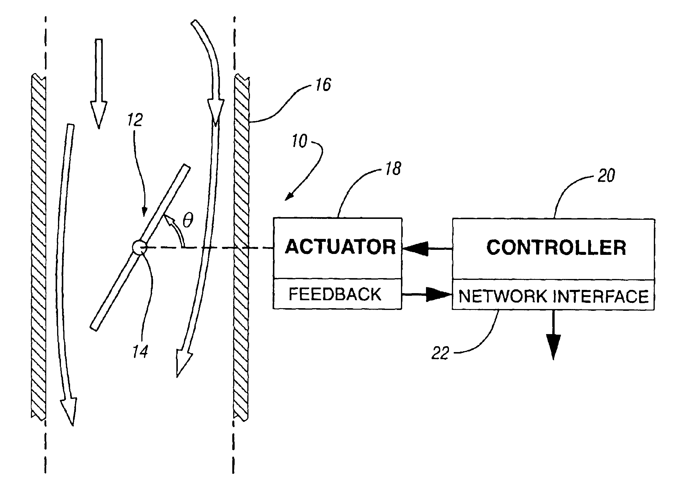
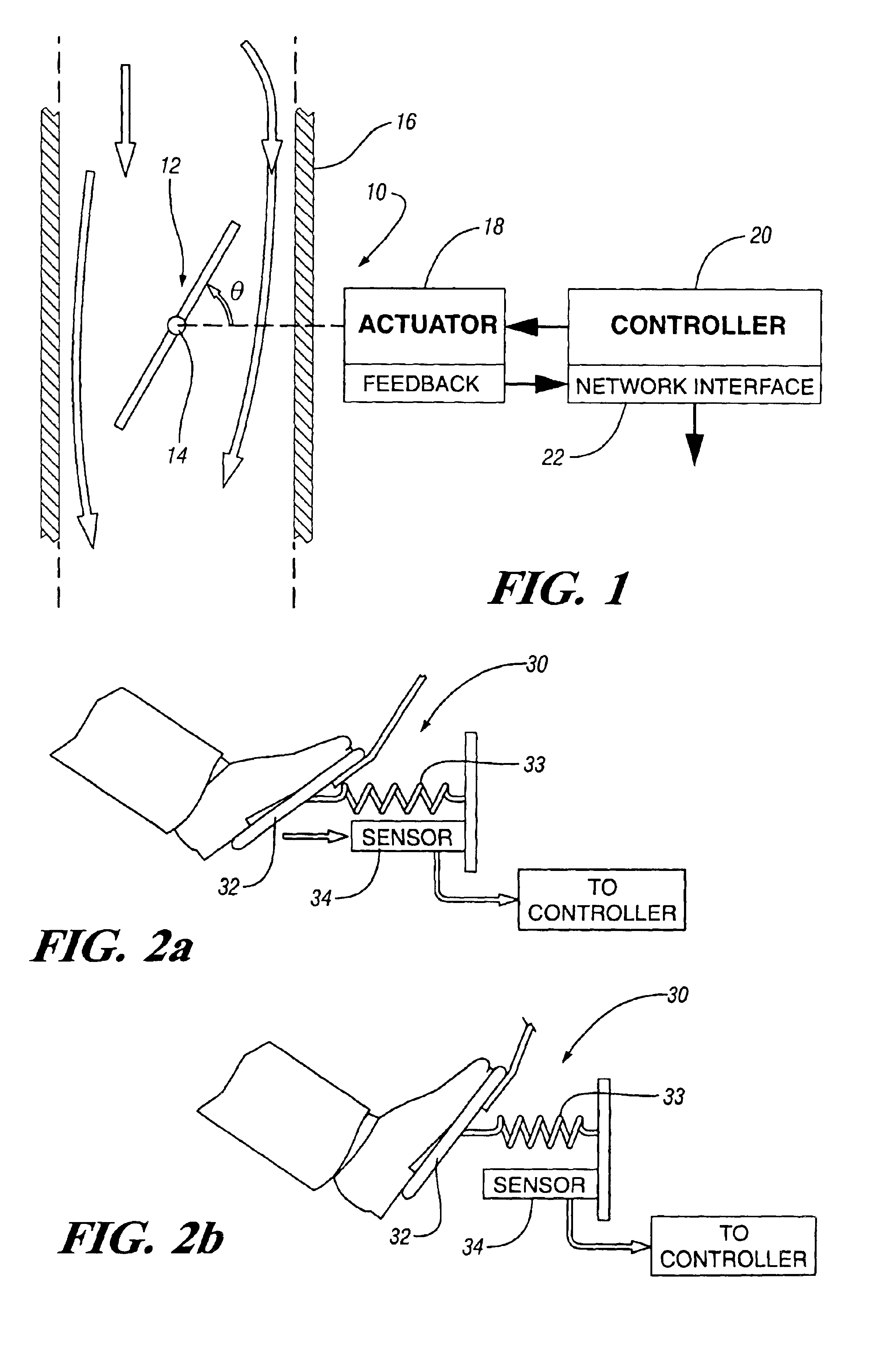
[0015]FIG. 1 is a diagrammatic drawing of an electronic throttle system 10 of the present invention. The system includes a throttle plate 12 which may be rotated to an angular position θ about pivot axis 14 within a throttle body 16 to control air flow to an internal combustion engine (ICE). If the angle θ is equal to zero, the throttle plate 12 will be in a position of maximum air flow constriction, and if the angle θ is equal to ninety degrees, the throttle plate 12 will be in a position of maximum air flow. Accordingly, the air flow may have varying flow rates when the angle θ is varied between zero and ninety degrees. The throttle plate is moved by an actuator 18 such as an electric motor. The electronic throttle system 10 may utilize any known electric motor or actuation technology in the art including, but not limited to, DC motors, AC motors, permanent magnet brushless motors, and reluctance motors.

[0016]An electronic throttle controller 20 includes power circuitry to modulat...


PUM


Abstract

An engine control system in a vehicle including an internal combustion engine, an electronic throttle controlling air flow to the internal combustion engine, a controller controlling the position of the electronic throttle, an accelerator pedal having an accelerator pedal sensor that generates a signal to the controller, and where the controller computes a rate of change for the accelerator pedal and actuates the electronic throttle to a desired position based upon the rate of change for the accelerator pedal.

Description

TECHNICAL FIELD[0001]The present invention relates to the control of internal combustion engines. More specifically, the present invention relates to a method and apparatus to control an electronic throttle.BACKGROUND OF THE INVENTION[0002]Electronic engine control has evolved from mechanical control systems employing simple switches and analog devices to a highly precise fuel and ignition control system employing powerful electronics. The miniaturization and cost reduction of electronics has put the power of the computer age into the hands of automotive engineers. Microprocessors have allowed complex programs involving numerous variables to be used in the control of present day combustion engines, leading to better engine control and performance.[0003]An important facet of combustion engine control is the regulation of air flow into a cylinder by a throttle and accordingly the quantity of fuel delivered into the cylinder. In an internal combustion engine (ICE), a throttle, having a...

Claims


Application Information

Patent Timeline
Patent Type & Authority Patents(United States)
IPC IPC(8): F02D11/10
CPCF02D11/106F02D2011/102F02D2200/0404
Inventor SRIPRAKASH, BHARGAV
Owner GM GLOBAL TECH OPERATIONS LLC
Why Eureka
Try Eureka