External control type fan-coupling device

Active Publication Date: 2005-07-12
USUI KOKUSAI SANGYO KAISHA LTD
View PDF64 Cites 20 Cited by
  • Summary
  • Abstract
  • Description
  • Claims
  • Application Information

AI Technical Summary

Benefits of technology

[0011]The external control type fan-coupling device according to the invention is enabled to reduce the size and weight of the electromagnet and to reduce the power consumption by mounting such a magnetic member in the non-magnetic case as transmits the magnetic flux of the electromagnet efficiently to the valve member (having the armature). Moreover, this magnetic member (or the magnetic loop element) is constructed either of the integral structure of the inner ring and the outer ring or the split structure, which is composed of a plurality of parts but is assembled into an integral structure and in which the inner ring and the outer ring are jointed preferably by brazing them with anon-magnetic material. Thus, the leakage of the magnetic flux of the electromagnetic coil can be suppressed to enhance the att

Problems solved by technology

In the case of the external control type fan-coupling device of the prior art, however, the electromagnets for activating the valve member and the armature are separated by the case of the non-magnetic member so that the magnetic force cannot be efficiently transmitted to the armature.
There arise problems that the size and weight of the electromagnets are enlarged, that the fan-coupling device can

Method used


Image

  • External control type fan-coupling device
  • External control type fan-coupling device
  • External control type fan-coupling device

Examples


Embodiment Construction

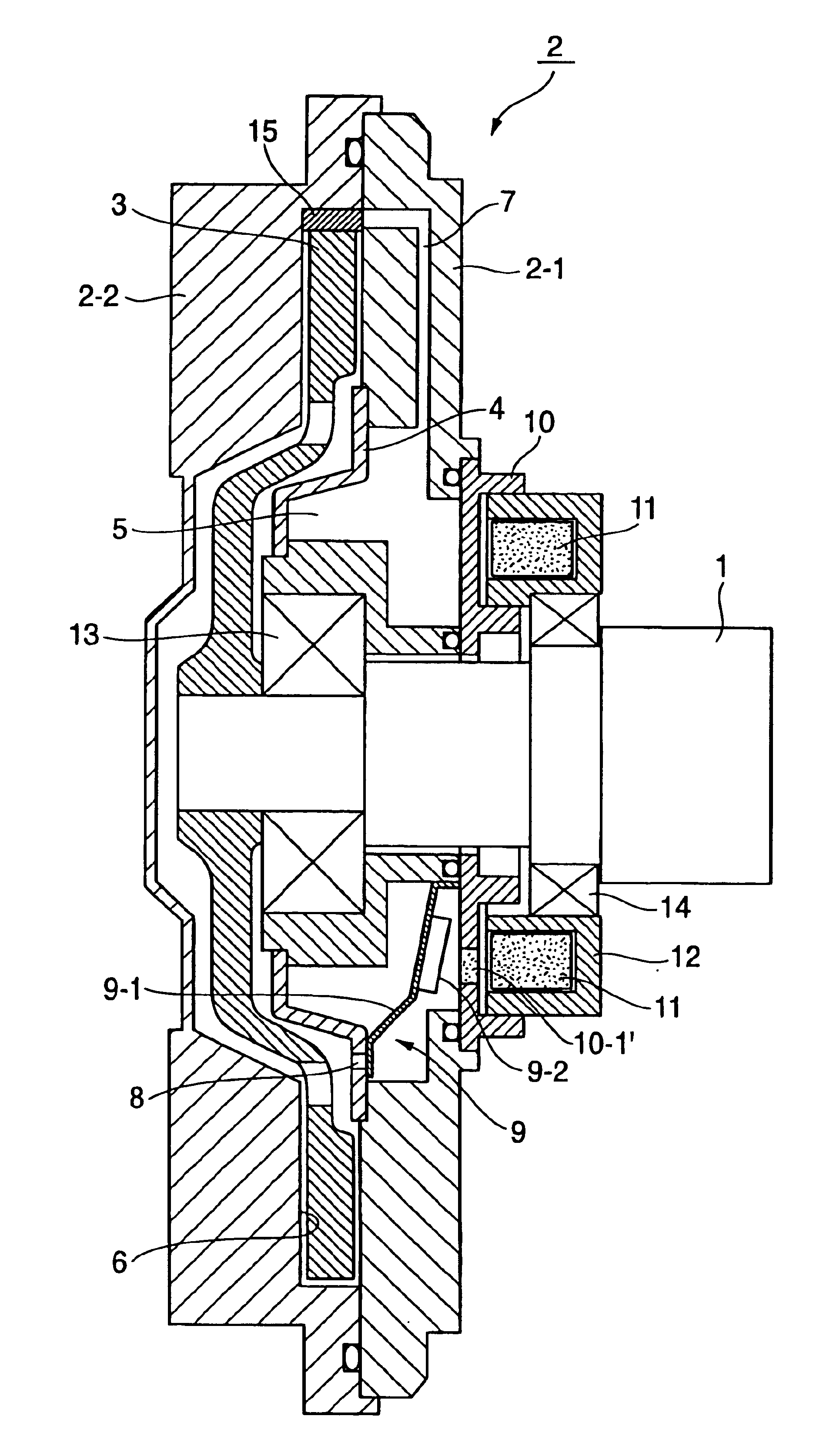
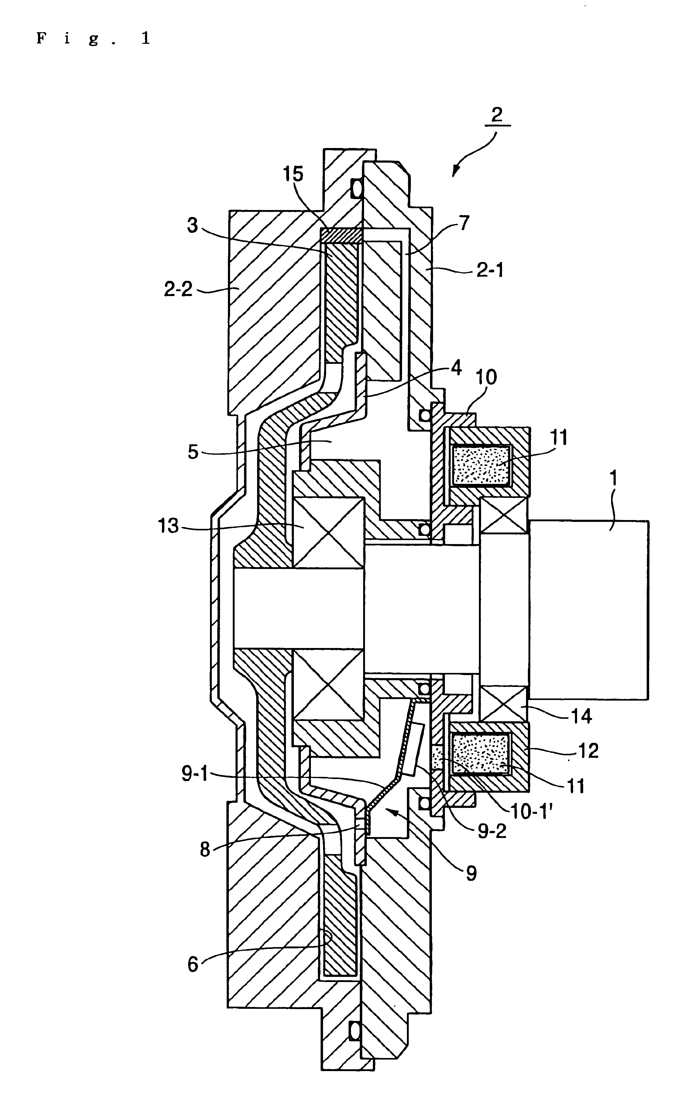
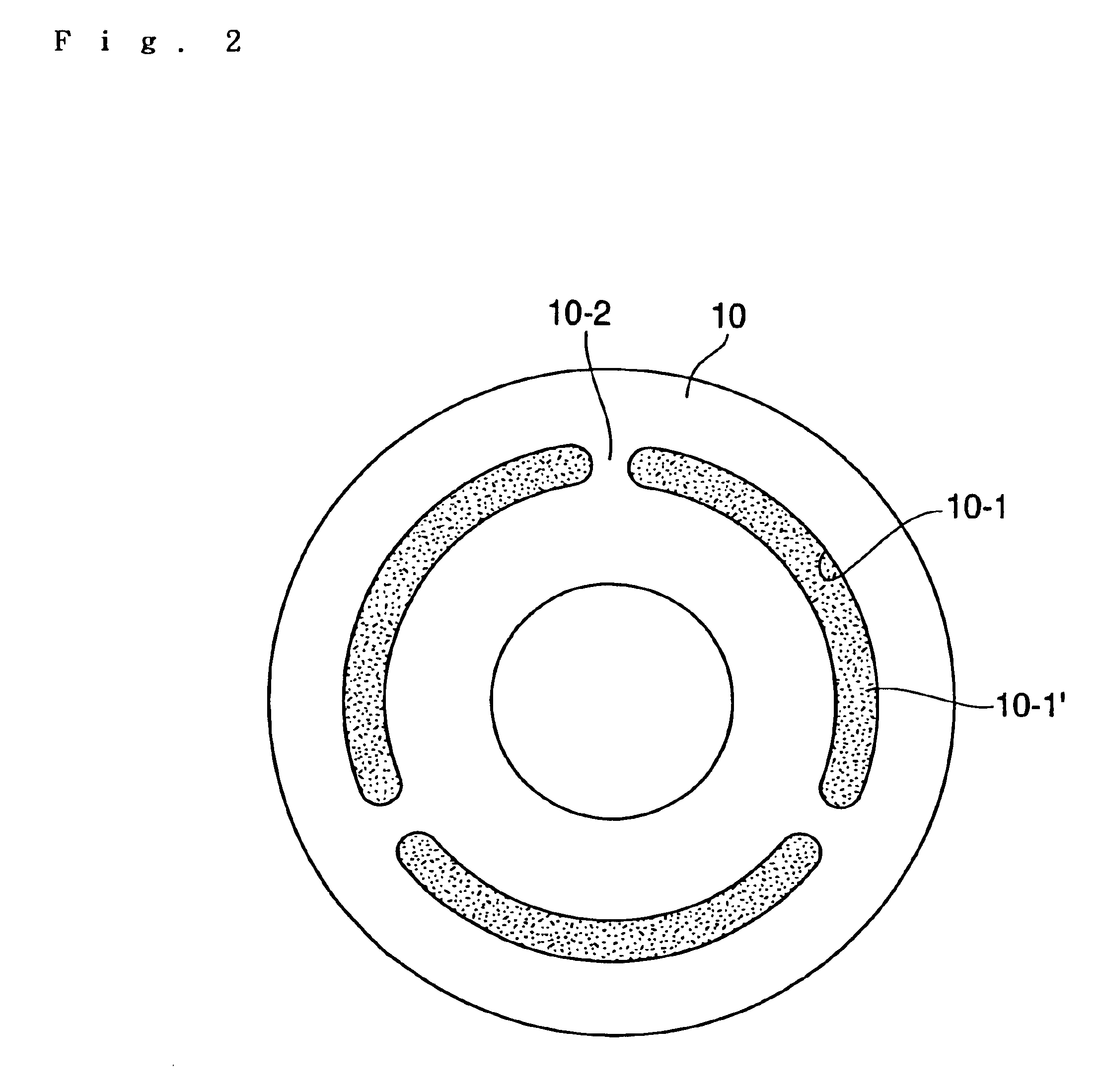
[0022]In FIG. 1 to FIG. 9: numeral 1 designates a rotary shaft member (or a drive shaft); numeral 2 a sealed housing; numeral 2-1 a case; numeral 2—2 a cover; numeral 3 drive disc; numeral 4 a partition; numeral 5 an oil sump; numeral 6 a torque transmission chamber; numeral 7 an oil recovering circulation passage; numeral 8 an oil feed adjusting hole; numeral 9 an oil feeding valve member; numeral 9-1 a leaf spring; numeral 9-2 an armature; numeral 10 a disc-shaped magnetic loop element (or a magnetic member) having a ring portion; numerals 20 and 30 ring-shaped magnetic loop elements (or a magnetic member); numeral 40 a non-ring-shaped magnetic loop element (or a magnetic member); numeral 11 an electromagnet; numeral 12 an electromagnet support; numerals 13 and 14 bearings; and numeral 15 a dam.

[0023]In the external control type fan-coupling device shown in FIG. 1, more specifically, the sealed housing 2 having the case 2-1 and the cover 2—2 is borne through the bearing 13 on the ...


PUM


Abstract

To reduce the size/weight and the power consumption of a fan-coupling device and to provide an external control type fan-coupling device intended to improve a fan rotation controllability.
A fan-coupling device, in which the inside of a sealed housing borne on a rotary shaft fixing a drive disk thereon is divided by a partition into an oil sump and a torque transmission chamber housing the drive disc, so that the drive torque may be transmitted to a driven side with the oil fed into the torque transmission chamber and so that the communication passage of oil may be opened/closed and controlled by a valve member to be activated by an electromagnet. In the fan-coupling device, a magnetic member of either an integral structure or a split structure composed of a plurality of parts and assembled integrally is arranged between the electromagnet and the valve member (or armature), and the magnetic member is so assembled in the sealed housing that the magnetic flux of the electromagnet may be transmitted through the magnetic member to the armature.

Description

BACKGROUND OF THE INVENTION[0001]1. Field of the Invention[0002]The present invention relates generally to an external control type fan-coupling device, in which an engine cooling fan rotation in an automobile or the like is controlled according to the temperature change in the surrounding, the change in the running condition of the engine or the like.[0003]2. Description of the Related Art[0004]In the prior art, there is a fan-coupling device of this kind, wherein the inside of a sealed housing composed of a case and a cover is divided by a partition having an oil feed adjusting hole into an oil sump and a torque transmission chamber housing a drive disc therein, wherein a dam formed is in such a portion, in which the oil accumulates at a rotating time, of the inner circumference wall face of the sealed housing side confronting the outer circumference wall portion of the drive disc, wherein an oil circulation passage is formed to lead to the dam between the torque transmission cham...

Claims


Application Information

Patent Timeline
IPC IPC(8): F16D33/18F16D35/02F16D35/00F16D33/00F16D33/08F01P7/08
CPCF16D33/08F16D33/18F16D35/024F16D35/02
Inventor SHIOZAKI, KENIIDA, YOSHINOBU
Owner USUI KOKUSAI SANGYO KAISHA LTD
Why Eureka
Try Eureka