Method of tracking tools

a technology of tracking tools and tools, applied in the field of tracking tools, can solve the problems of inability to positively identify the origin of the tool, the current system of controlling the tool does not provide for total tool accountability, and the information left in the engine of the aircraft could damage the engine and perhaps the whole plane, so as to protect against information loss, the effect of being readily available for later us

Inactive Publication Date: 2005-07-12
UFP TECHNOLOGIES
View PDF11 Cites 10 Cited by
  • Summary
  • Abstract
  • Description
  • Claims
  • Application Information

AI Technical Summary

Benefits of technology

[0018]One advantage of a data matrix symbology over a conventional linear bar code is that it is more reliably readable by a scanner. A conventional linear bar code requires at least eighty-percent contrast to be readable by a scanner, whereas data matrix symbology requires only a twenty-percent contrast. The data matrix symbology will also resist loss of information due to physical damage to the surface on which the code has been applied.
[0020]The greater storage capabilities of the data matrix symbology can be used to resist loss of information due to damage of the coded portion of the tool by providing redundant recitations of the recorded information within the same coded area. Further protection against loss of information is provided by applying the data matrix symbology at two locations on the surface of the tool.

Problems solved by technology

The current systems for controlling tools do not provide for total tool accountability.
For example, using currently available tool control systems, when a tool is found on an airplane, its origin cannot be positively identified.
A tool left in the engine of an aircraft could damage the engine and perhaps the whole plane.
The danger becomes compounded during military exercises and missions when fighters returning from a mission must be refueled and rearmed within a minimum time and returned to combat.
The technology is currently available to print information on any tool in a form that is readable with the human eye; however, space limitations on the surface of the tool limit the amount of information that can be visually readable.
Prior efforts to use a traditional bar scanner or computerized tracking and computer readable codes to monitor tools have not been successful for a number of reasons.
Because of their functional nature, tools have surfaces, which in the past have been considered unsuitable for receiving the known methods of applying a conventional bar code of the type readable or scannable code by a computer.
A linear bar code requires a flat surface and for some tools there are no flat surfaces suitable for receiving a conventional bar code.
The material of which the tool is made is also functional and is generally unsuitable for receiving a conventional bar code.
The chrome surface provides a function, which extends the useful life of the tool, but chrome is reflective and electronic codes applied to a chrome surface using existing technology are unreadable by a scanner because the scanner is unable to detect sufficient contrast between marked and unmarked portions of the surface.
Black oxide surfaces are totally non-reflective and electronic codes applied to black oxide using existing technologies are also unreadable.
Similarly, plastic, rubber, and wood are not suitable media for receiving readable electronic codes.
It is also unsatisfactory to provide a label to be attached to the surface of a tool because there is a risk that the label itself may become detached from the tool and become a source of FOD.
If wear of the type ordinarily suffered to the surface of a tool will render the electronic coding on the surface unreadable, the tool will not be identifiable when it is found on a plane and the system will have failed when it is needed most.

Method used


Image

  • Method of tracking tools
  • Method of tracking tools
  • Method of tracking tools

Examples


Embodiment Construction

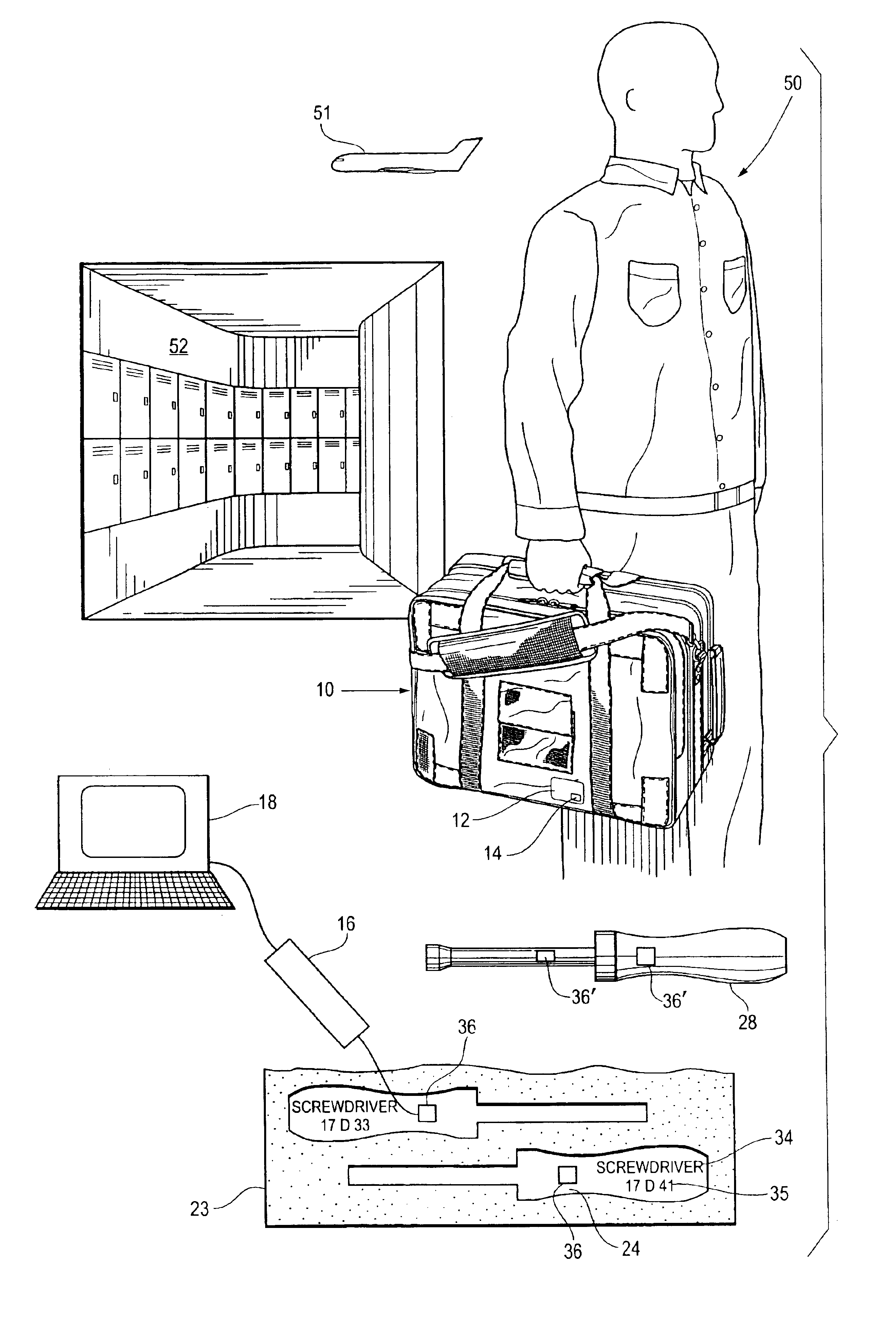
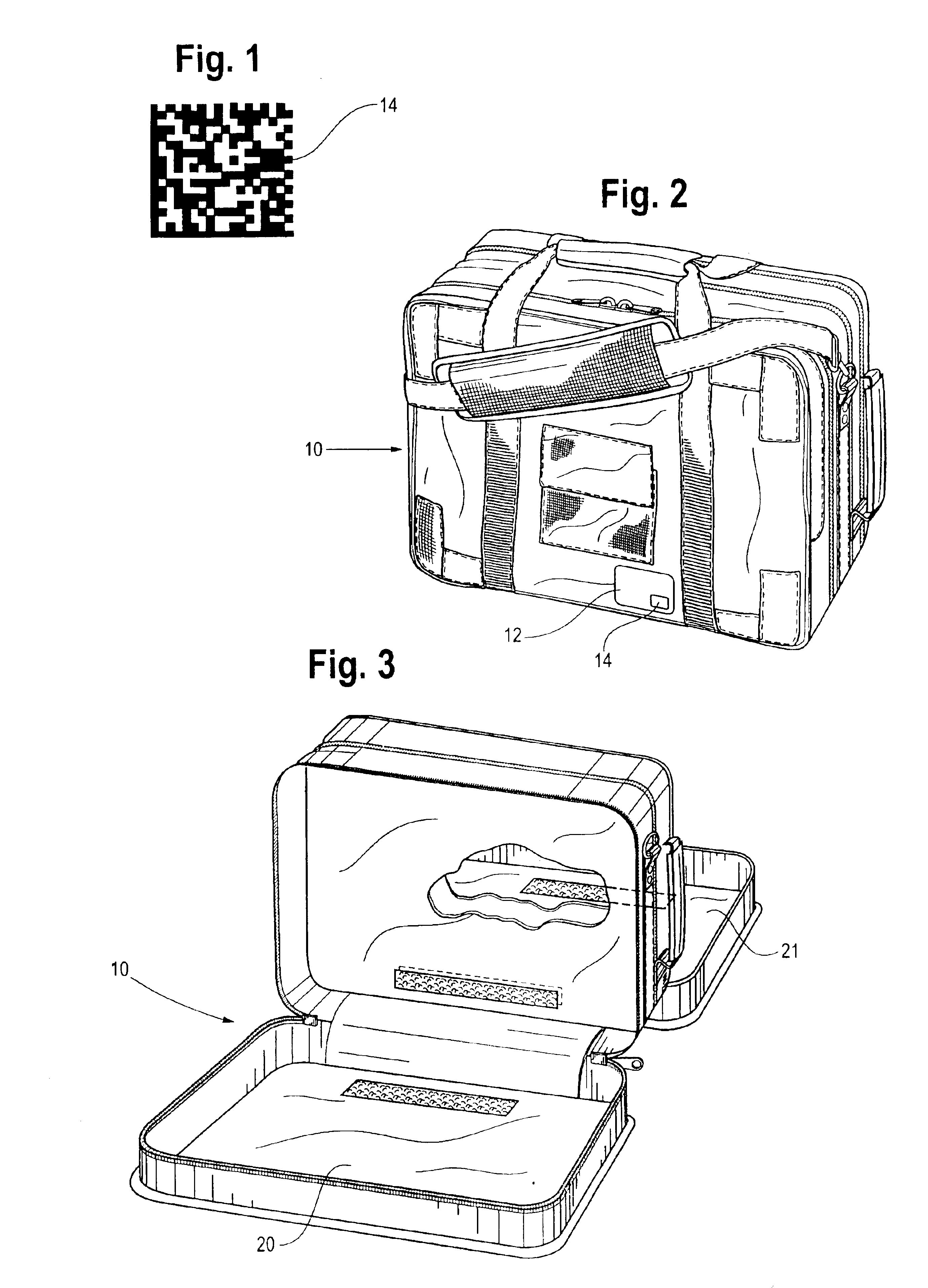
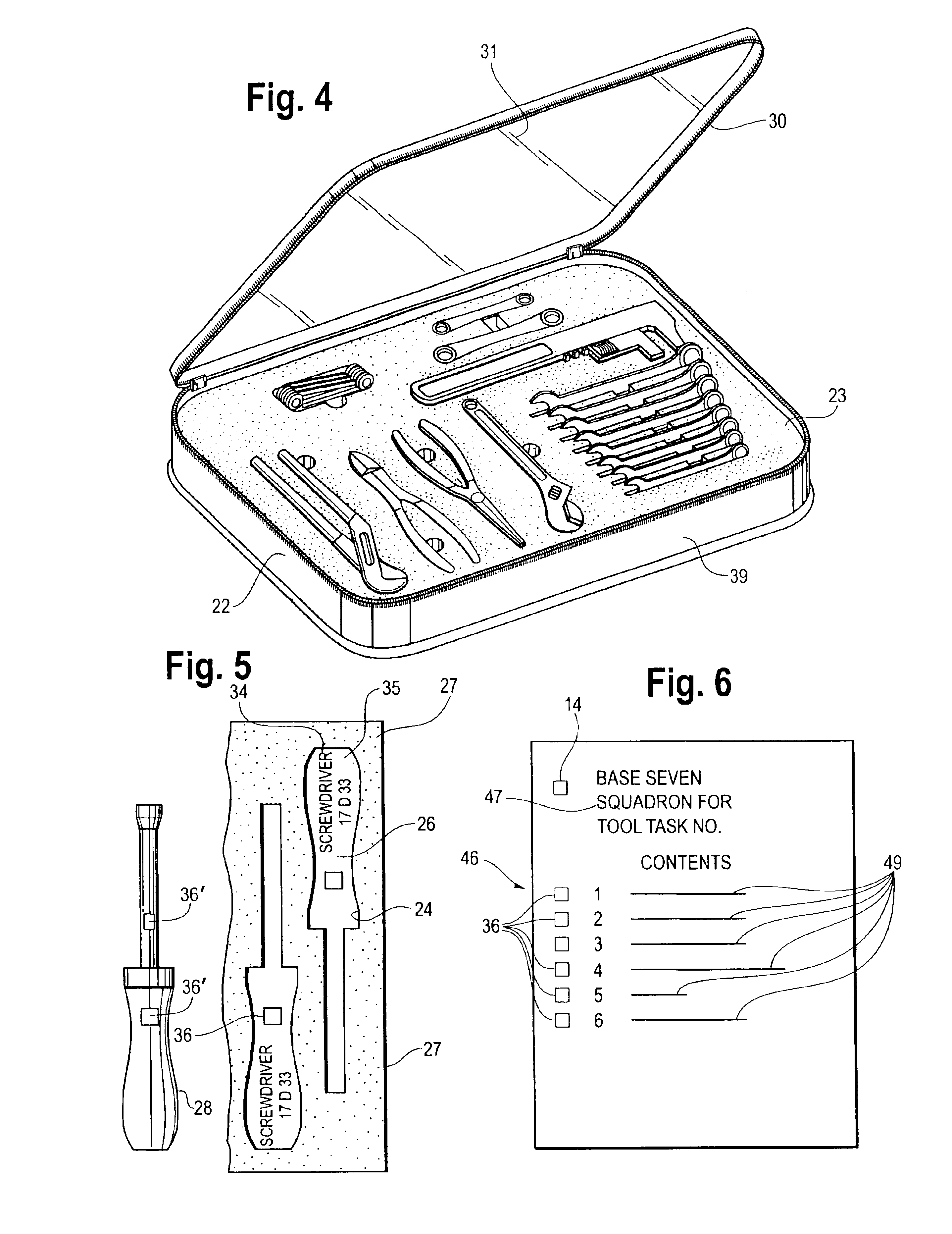
[0030]Referring to FIGS. 1-5 and 7, a set of tools needed to perform a task on a military base are stored in a suitable storage means. The most commonly used means of storing tools is a tool box having a plurality of drawers with the tools of the box laid out so that all the tools in the drawer are visible when the drawer is opened. Another commonly used method is to retain the tools on vertical boards, which line the perimeter of a work area. A third method used by mechanics who service combat planes that have returned from one mission and are to be made ready for a subsequent mission, employs a flexible bag that has a number of zippered compartments with two pallets of tools stored in each of the compartments. There are other methods of storing tools, but these are the methods most commonly used.

[0031]Referring to FIGS. 2 through 5, the tools of a certain set are, for the purpose of this discussion, stored in a flexible bag 10. The bag 10 has on its outer surface an identification...


PUM


Abstract

To track a large number of tools, the tools are kept in sets with each set having a container. A silhouette of each tool stored in the container is printed at the point of storage along with a dat matrix code that has stored in binary code a description of the tool, the part number, and an identification of the kit of which it is a part. The associated tool has etched into the surface thereof a data matrix code containing the same information as the code printed at the point of storage. The data matrix codes are readable by a scanner and a record of all the tools is maintained on a computer.

Description

[0001]This is a continuation of my co-pending application filed Jan. 22, 2003 and assigned Ser. No. 10 / 349,056. The present invention relates to a system for identifying, controlling, and tracking tools in an environment in which the misplacing of a single tool can have serious financial, productivity, and safety consequences, and in particular a method for providing an electronic control for the use of every tool utilized in the manufacturing operation and technical service function. The invention is a tool management system in which electronically scan / read technology is used to read 2D Data Matrix symbology from tool surfaces previous considered to be unsuited for receiving scannable electronic codes.BACKGROUND OF THE INVENTION[0002]The current systems for controlling tools do not provide for total tool accountability. Total accountability requires that every tool have a place, every tool must be in its place, and for any tool that is not in its place a trail leads to the last a...

Claims


Application Information

Patent Timeline
Patent Type & Authority Patents(United States)
IPC IPC(8): G06Q10/00G06Q10/06
CPCB25H3/00G06Q10/06
Inventor ALLEN, PHILIP L.
Owner UFP TECHNOLOGIES
Why Eureka
Try Eureka