Device for handling an appliance to be implanted

a technology for implanting devices and appliances, applied in the field of medical devices, can solve the problems of low life-saving rate and high risk of surgically implanting artificial blood vessels for the treatment of aortic aneurysms, and achieve the effects of preventing bleeding, improving accuracy and efficiency of implanting the appliance to be implanted, and connecting smoothly

Inactive Publication Date: 2005-07-12
KANJI INOUE
View PDF76 Cites 71 Cited by
  • Summary
  • Abstract
  • Description
  • Claims
  • Application Information

AI Technical Summary

Benefits of technology

[0037]If the front end of the device for transporting the appliance is engaged with the appliance to be implanted and the base end of the device for transporting the appliance is turned down so as to be caught by the catcher, it becomes easy to arrange the device for transporting the appliance at a position where it is easy for the catcher to catch. As a result of this, the accuracy and the efficiency of implanting the appliance to be implanted is effectively improved.
[0038]During the above process if a guide pipe having a valve is used, it becomes possible to guide the base end of the device for transporting the appliance to a position preferable to be caught with not only preventing bleeding but also preventing the device for transporting the appliance from entangling in the appliance to be implanted.
[0039]If a pair of the appliances to

Problems solved by technology

The above-mentioned method of surgically implanting the artificial blood vessel for treatment of aortic aneurysm, however, is highly dangerous.
Especially, an emergency operation for treatment of a ruptured aneurysm has a low life-saving rate, and an operation of dissecting aortic aneurysm is difficult to conduct and has a high death rate.
However, if such an intermediate wire ring is attached to the tubular cover, the appliance is easily prevented from being folded.
However, as the tubular cover is made of a sheet, the locally formed wrinkles do not bring about transformations at the center of the tubular cover.
Therefore, for example, if the whole area of the circumference of the intermediate wire ring is fixedly connected to the tubular cover, the center of the tubular cover is dragged at the specified positions of the circumference thereof toward the direction of the peak or the valley along the wavy shape of the intermediate wire ring and the whole tubular cover tends to be bulky as well as unfavorable load is applied to the intermediate wire ring because of the sliding re

Method used


Image

  • Device for handling an appliance to be implanted
  • Device for handling an appliance to be implanted
  • Device for handling an appliance to be implanted

Examples


Embodiment Construction

[0111]The invention will be described in detail with reference to the embodiments thereof shown in the accompanying drawings.

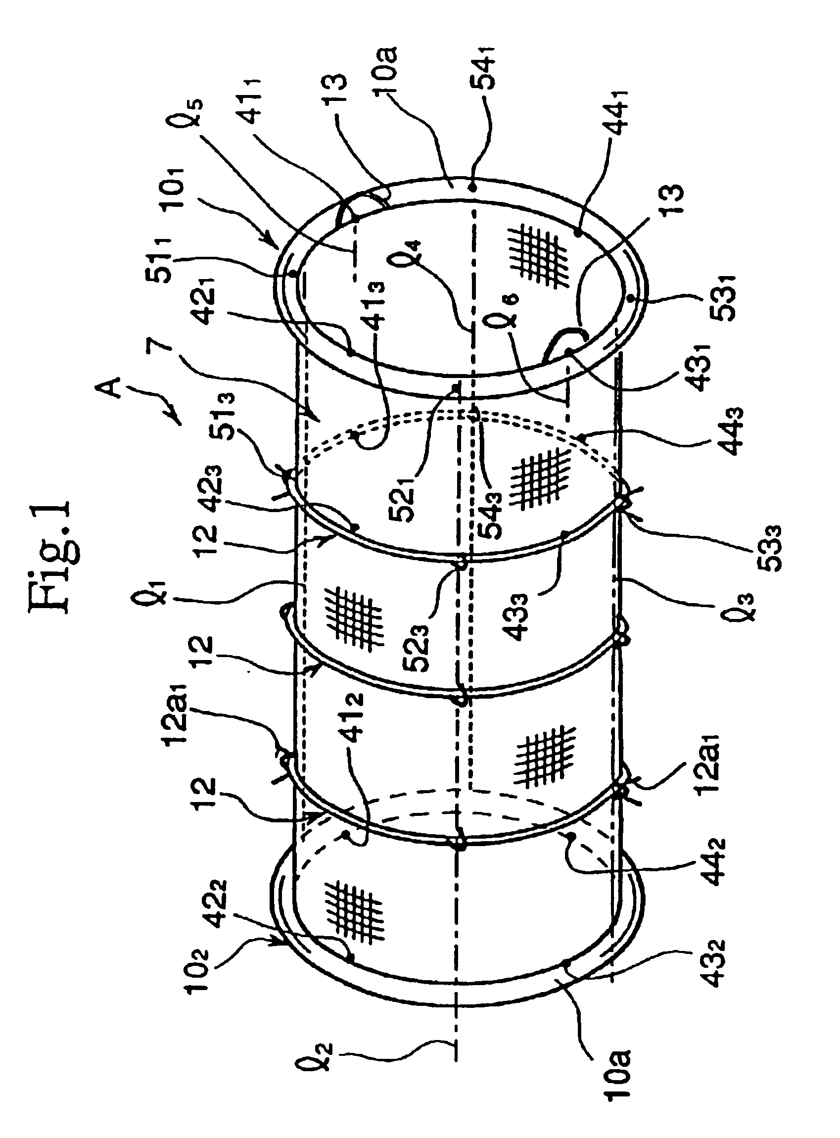
[0112]The artificial blood vessel A as the appliance to be implanted, which is collapsed by the method in accordance with this invention, comprises, as shown in FIG. 1, a cover 7, end wire rings 101, 102 and intermediate wire rings 12.

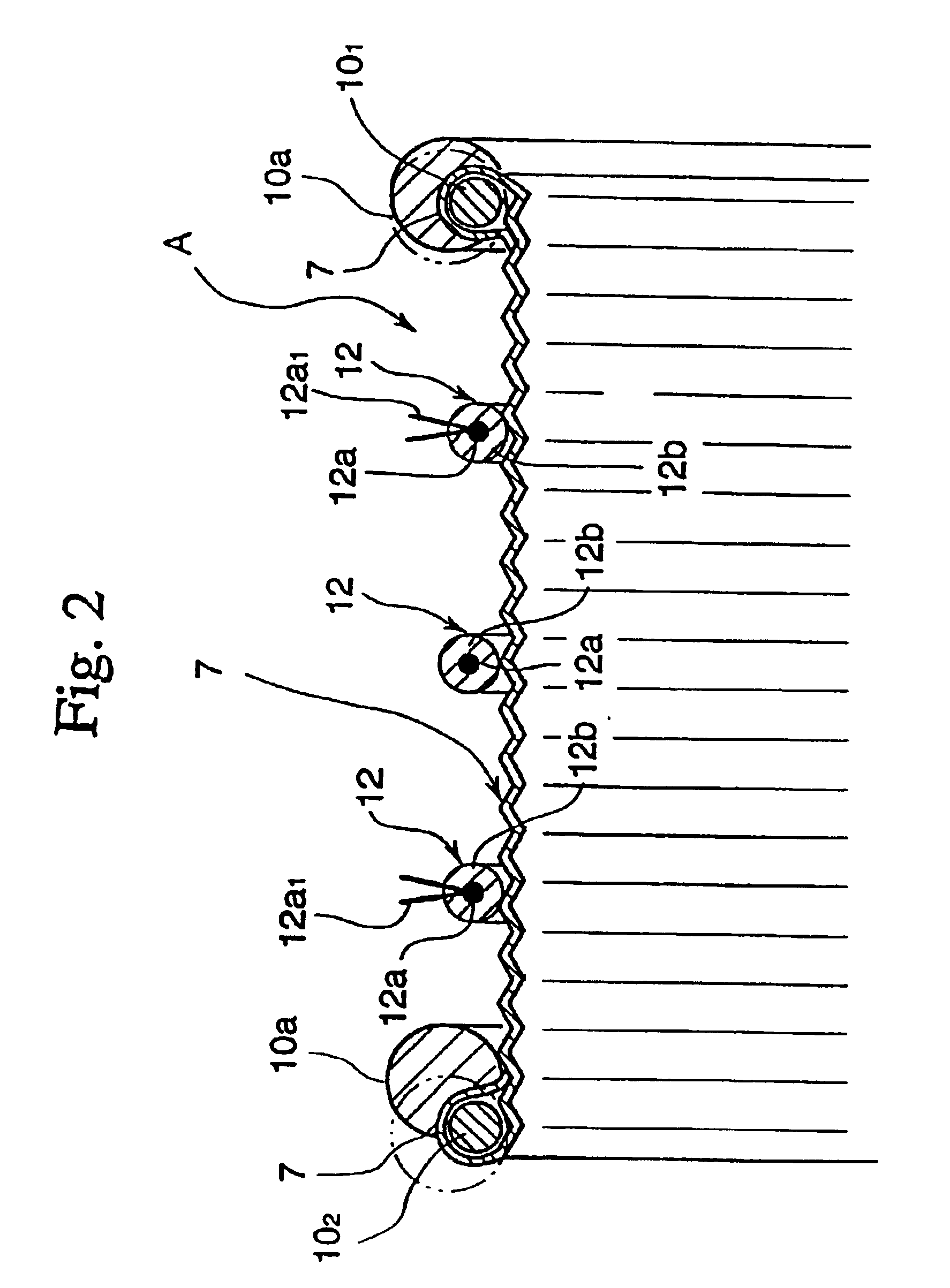
[0113]The cover 7, as shown in FIG. 2, consists of a flexible, tensile sheet shaped into a tube of bellows, the normal diameter of which generally corresponds to the shape of that portion of the human blood vessel at which the artificial blood vessel A is to be implanted. The sheet of the cover 7 is, for example, of warps extending in the axial direction of the artificial blood vessel A woven with wefts extending in the circumferential direction thereof, wherein the warps are of mono-filament made of polyester (about 15 denier) and the wefts are of multi-filament made of a plurality of superfine filaments (about 50 denier) interw...


PUM


Abstract

The artificial blood vessel A comprises a front end wire ring 101, a rear end wire ring 102 arranged facing to the front end wire ring 101, a tubular cover 7 which connects the end wire rings 101, 102, and a plurality of intermediate wire rings 12 arranged spaced apart from each other between the front end wire ring 101 and the rear end wire ring 102. Each of the front end wire ring 101, the rear end wire ring 102 and the intermediate wire rings 12 are given flexibly foldable elasticity. The circumference of the front end wire ring 101 is equally divided into four by dividing points 411, 421, 431, 441. Hooking means 13 are formed for a front pull string to be passed through at the dividing points 411, 431. The circumference of the intermediate wire ring 12 is fixed to the tubular cover 7 by suturing or with adhesive at the positions 513, 523, 533, 543 which correspond to the midpoint 511 between the dividing points 411, 421, the midpoint 521 between the dividing points 421, 431, the midpoint 531 between the dividing points 431, 441, and the midpoint 541 between the dividing points 441, 411.

Description

[0001]This application is a divisional of U.S. application Ser. No. 09 / 635,706, filed Aug. 9, 2000, now U.S. Pat. No. 6,471,722, which is a continuation of U.S. application Ser. No. 09 / 119,850, filed Jul. 21, 1998, now U.S. Pat. No. 6,183,504, which is a divisional of U.S. application Ser. No. 08 / 898,427, filed Jul. 22, 1997, now U.S. Pat. No. 5,925,076, which is a divisional of U.S. application Ser. No. 08 / 765,216, filed Jan. 3, 1997, now U.S. Pat. No. 5,843,162, which is a 371 of PCT / JP96 / 01347 filed May 17, 1996, which claims priority to PCT / JP95 / 00972 filed May 19, 1995.FIELD OF THE ART[0002]This invention relates to appliances for medical treatment and, more particularly, to an appliance collapsible for insertion into a human organ and capable of resilient restoration (which will be referred to as “the appliance to be implanted” in this specification and claims), to a method of collapsing the appliance to be implanted, and to a method of using the collapsed appliance to be impl...

Claims


Application Information

Patent Timeline
IPC IPC(8): A61F2/06A61F2/966A61M29/00A61M29/02A61M39/00
CPCA61F2/07A61F2/954A61F2/97A61F2/86A61F2002/065A61F2002/072A61F2002/075A61F2002/9505A61F2002/9511A61F2002/9522Y10S623/903A61F2/89A61F2/9522A61F2/9525
Inventor KANJI, INOUE
Owner KANJI INOUE
Why Eureka
Try Eureka