Lighting apparatus with enhanced capability of removing heat

a technology of lighting apparatus and heat removal, which is applied in the direction of lighting and heating apparatus, fixed installation, semiconductor devices for light sources, etc., can solve the problems of large amount of electricity supplied to leds, heat reduces the quantity of light from leds, and does not have a very high luminous efficacy presently, so as to reduce the size or weight of lighting apparatus, and efficiently conduct heat

Inactive Publication Date: 2005-07-12
PANASONIC CORP
View PDF8 Cites 24 Cited by
  • Summary
  • Abstract
  • Description
  • Claims
  • Application Information

AI Technical Summary

Benefits of technology

[0010]With this arrangement, it is possible to remove the heat from a lighting apparatus by having the fluid flow in the passage to efficiently conduct the heat from the luminous elements (e.g. LEDs) mounted on a substrate. Furthermore, it is possible to avoid increasing the size or weight of the lighting apparatus, because the lighting apparatus of the present invention does not require a cooling member such as a radiator board nor space for dissipating the heat from the radiator board into the air.

Problems solved by technology

LEDs, however, do not have very high luminous efficacy presently and a large part of electricity supplied to LEDs turns into heat.
There are problems that the heat reduces the quantity of light from the LEDs, or in a worst case, the heat damages the LEDs.
In order to solve the problems, there is an idea to install a heat sink on the back of a substrate on which LEDs are mounted; however, with this idea one of the benefits of the LED lighting apparatuses of being compact would be lost, because a cooling member needs to be installed as well as another device for dissipating the heat conducted to the cooling member.

Method used


Image

  • Lighting apparatus with enhanced capability of removing heat
  • Lighting apparatus with enhanced capability of removing heat
  • Lighting apparatus with enhanced capability of removing heat

Examples


first embodiment

[1] General Structure

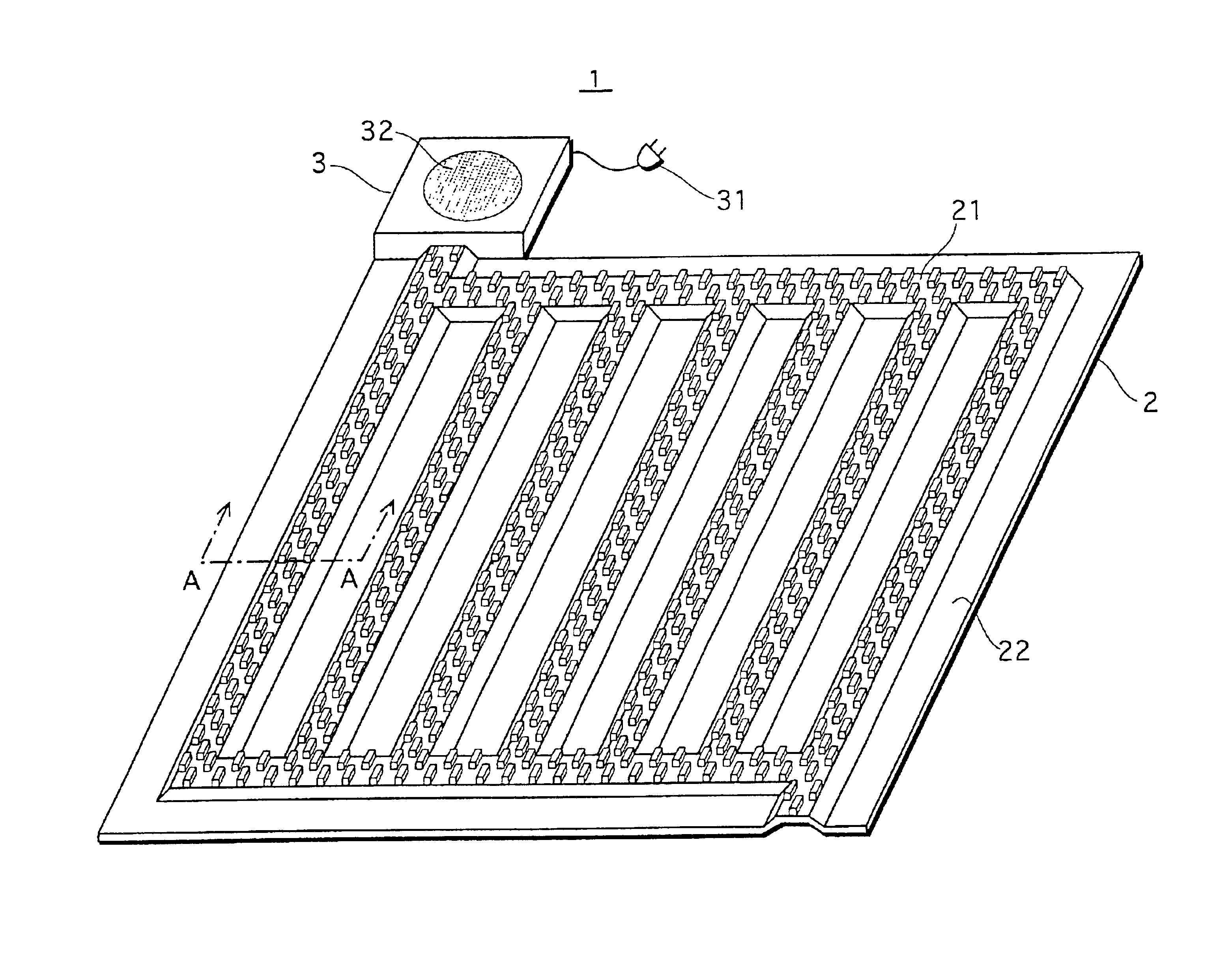
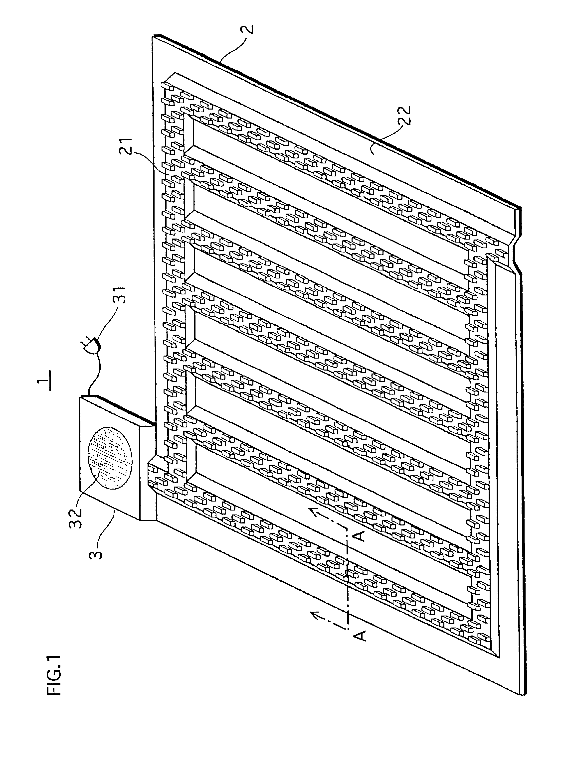
[0025]The following describes the general structure of the lighting apparatus of the first embodiment with reference to FIG. 1. FIG. 1 is a perspective view of the lighting apparatus as seen by looking down on its exterior. The lighting apparatus 1 comprises an LED-mounted substrate 2 and an exhauster 3. The LED-mounted substrate 2 has a raised area 21 of trapezoidal cross section, and a flat area 22. A large number of LEDs are mounted on the raised area 21 of the LED-mounted substrate 2.

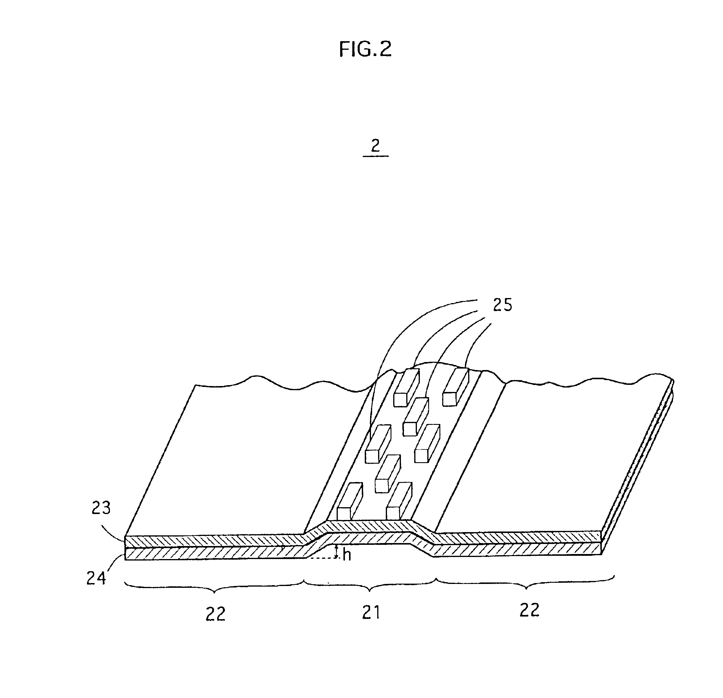
[0026]FIG. 2 is a perspective sectional view of the raised area 21 from the cross section A—A. The LED-mounted substrate 2 is made up of a flexible substrate 24 with the Cu pattern 23 formed thereon. The flexible substrate 24 is made of glass epoxy (glass fiber reinforced plastic). The height h of the raised area 21 measured from the level of the flat area 22 is arranged so that h is equal to or larger than a half of the thickness of the flexible substrate 24. And, SMD (Surface ...

second embodiment

[0037]The following describes a lighting apparatus of the second embodiment with reference to the drawings:

[0038]Whereas it is designed to remove heat by having air flow through the passage enclosed by the raised area 21 and a wall in the first embodiment, it is designed to remove heat by circulating a cooling gas in a more active manner in the second embodiment. Examples of cooling gases are so-called CFC Substitutes such as HCFC (Hydrochlorofluorocarbon) and HFC (Hydrofluorocarbon).

[1] General Structure

[0039]FIG. 6 is a perspective view of the lighting apparatus in the second embodiment as seen by looking down on its exterior. The lighting apparatus 5 comprises an LED-mounted substrate 7 and a heat remover 6. The LED-mounted substrate 7 has a raised area 71 of trapezoidal cross section, and a flat area 72. A large number of LEDs are mounted on the raised area 71 of the LED-mounted substrate 7.

[0040]FIG. 7 is a perspective sectional view of the raised area 71 from the cross section...

third embodiment

[0048]It is also desirable to remove the heat from LEDs using a liquid adjusted to be a predetermined temperature. The explanation on the structure and production method for the LED-mounted substrate in this embodiment will be omitted as it is the same as the second embodiment.

[0049]FIG. 9 shows the general structure of the lighting apparatus 8 in the third embodiment. In FIG. 9, a valve 100 adjusts the amount of the cooling liquid that flows into the passage of the LED-mounted substrate 9. The cooling liquid goes through the valve 100, flows into the passage from the opening of the passage 911, absorbs the heat from LEDs while it flows through the passage, and flows out from the opening 912. The cooling liquid coming out of the opening 912 will be discharged via a discharge pipe 101.

Modifications

[0050]This invention so far has been explained on the basis of the preferred embodiments; however, needless to say, the embodiments of this invention are not limited to the ones mentioned a...


PUM


Abstract

A lighting apparatus comprises an LED-mounted substrate and an exhauster. The substrate has a flat area as well as one or more raised areas of trapezoidal cross section which each form a passage thereunder. LEDs are mounted on the raised areas. When the LED-mounted substrate is installed on a wall, the passages are enclosed by the wall. The exhauster removes the heat from the LEDs by drawing out the air going through inside the passages.

Description

[0001]This application is based on an application No. 2001-282246 filed in Japan, the content of which is hereby incorporated by reference.BACKGROUND OF THE INVENTION[0002](1) Field of the Invention[0003]The present invention relates to lighting apparatuses mainly with LEDs (Light Emitting Diodes), and more particularly heat removing methods for such lighting apparatuses.[0004](2) Description of the Related Art[0005]Lately, lighting apparatuses with LEDs have been attracting attention as next-generation lighting apparatuses to take over fluorescent lamps and the like. The lighting apparatuses with LEDs have advantages in compactness and a long life span over incandescent lamps, fluorescent lamps and mercury lamps.[0006]LEDs, however, do not have very high luminous efficacy presently and a large part of electricity supplied to LEDs turns into heat. There are problems that the heat reduces the quantity of light from the LEDs, or in a worst case, the heat damages the LEDs.[0007]In orde...

Claims


Application Information

Patent Timeline
Patent Type & Authority Patents(United States)
IPC IPC(8): F21V29/02F21V29/00F21S8/04F21S8/00H01L25/075H01L33/00F21S2/00F21Y101/02H01L33/48H01L33/62H01L33/64H05K7/20
CPCF21K9/00F21V29/02F21V29/30F21S8/033F21S8/04F21Y2101/02H01L25/0753H01L33/648H01L2924/0002H01L2924/00F21Y2115/10F21V29/56F21V29/51
Inventor MATSUI, NOBUYUKINAGAI, HIDEOTAMURA, TETSUSHIHATADA, KENZO
Owner PANASONIC CORP
Why Eureka
Try Eureka