

Optical device and projector
A technology of optical devices and dimming devices, which is applied in the fields of projectors and optical devices, can solve problems such as increased heat density, insufficient cooling of liquid crystal panels, and difficulty in fully utilizing the performance of liquid crystal panels, so as to improve cooling performance, enhance strength, Effect of improving cooling performance
- Summary
- Abstract
- Description
- Claims
- Application Information
AI Technical Summary
Problems solved by technology
Method used
Image

Examples
no. 1 Embodiment approach
[0181] Next, a first embodiment of the present invention will be described with reference to the drawings.
[0182] (1. The main structure of the projector)
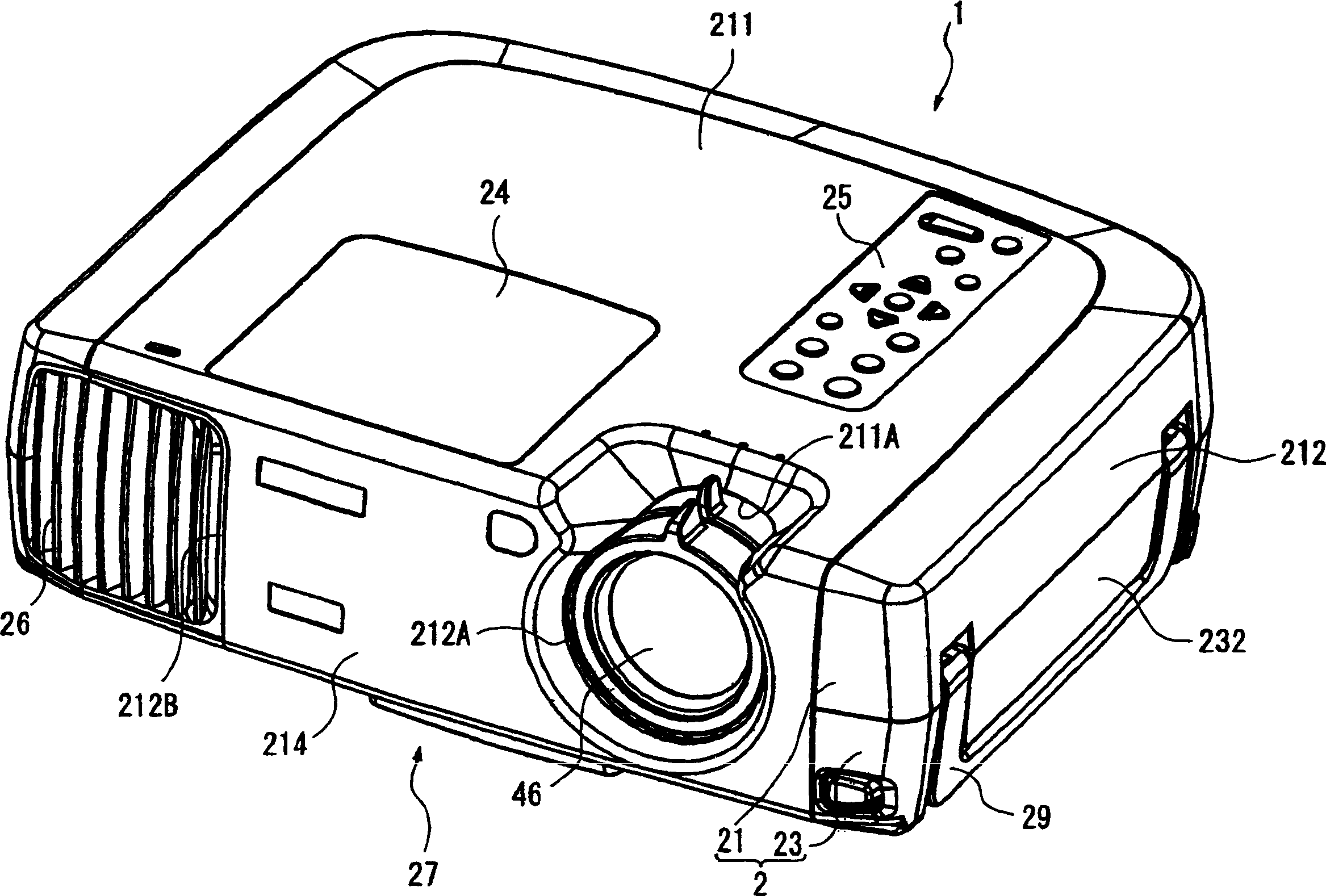
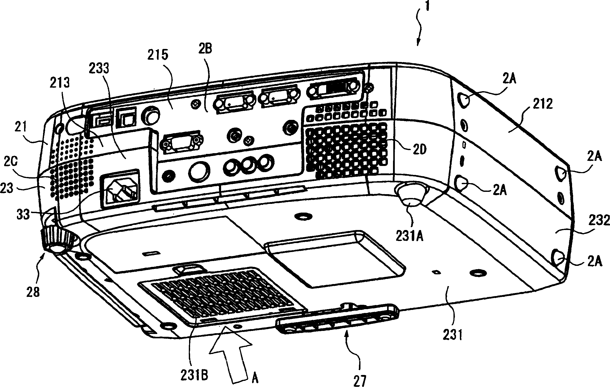
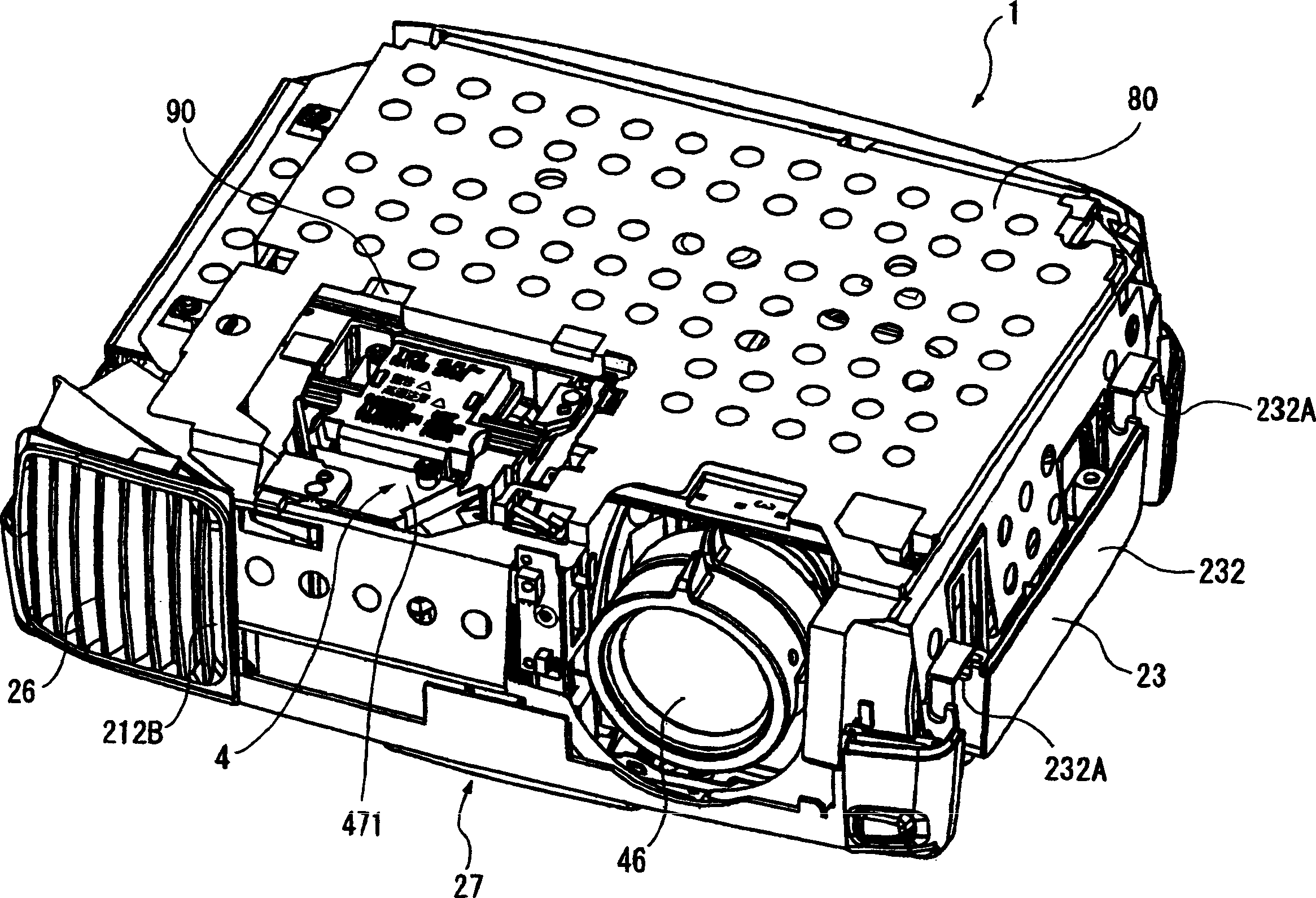
[0183] figure 1 is an overall perspective view of the projector 1 according to the first embodiment viewed from above, figure 2 is an overall perspective view of the projector 1 viewed from below, Figure 3 to Figure 5 It is a perspective view showing the inside of the projector 1 . Specifically, image 3 From figure 1 The figure when the upper box body 21 of the projector 1 is unloaded in the state of Figure 4 From image 3The figure seen when the shield plate 80, the drive plate 90, and the upper housing 472 are removed and viewed from the rear side, Figure 5 From Figure 4 The state shows the removal of the optical unit 4. The components 4, 21, 80, 90, 472 constituting the projector will be described in detail below.
[0184] exist Figure 1 to Figure 5 Among them, the projector 1 is equipped with an out...
no. 2 Embodiment approach
[0288] Next, a second embodiment of the present invention will be described.
[0289] In the following description, the same structure and the same member as those of the above-mentioned first embodiment are given the same reference numerals, and their detailed descriptions are omitted or simplified.
[0290] In the optical device of the first embodiment described above, the holding member 446 is provided with a rectangular plate-shaped body 446A and pins 447A protruding from four corners of the rectangular plate-shaped body 446A. On the other hand, the optical device of the second embodiment is different in that, as shown in FIG. 15 , the holding member 446 has a standing piece 447B having a substantially L-shaped front surface. Other configurations and manufacturing methods are the same as those of the first embodiment. In addition, the materials described in the first embodiment can be used for the materials of the respective components.
[0291] Specifically, the upright...
no. 3 Embodiment approach
[0295] Next, a third embodiment of the present invention will be described.
[0296] In the following description, the same structures and the same components as those of the first embodiment are given the same reference numerals, and detailed descriptions thereof are omitted or simplified.
[0297] In the optical device of the first embodiment described above, the holding member 446 is provided with a rectangular plate-shaped body 446A and pins 447A protruding from four corners of the rectangular plate-shaped body 446A. On the other hand, the optical device of the third embodiment is different in that, as shown in FIG. 16 , a holding member 446 is provided with a standing piece 447C having a substantially L-shaped front surface. Other configurations and manufacturing methods are the same as those of the first embodiment. In addition, the same materials as those described in the first embodiment can be used for the materials of various components.
[0298] Specifically, the ...
PUM
| Property | Measurement | Unit |
|---|---|---|
| thermal conductivity | aaaaa | aaaaa |
| thermal conductivity | aaaaa | aaaaa |
| thermal conductivity | aaaaa | aaaaa |
Abstract
Description
Claims
Application Information