Multielement planar antenna

a multi-element, antenna technology, applied in the direction of individual energised antenna arrays, resonant antennas, array feeding systems, etc., to achieve the effect of reducing the length of the feeding line, reducing the number of matching circuits, and facilitating the design of multi-element planar antennas for higher functionality

Inactive Publication Date: 2005-07-12
NIHON DEMPA KOGYO CO LTD +1
View PDF3 Cites 16 Cited by
  • Summary
  • Abstract
  • Description
  • Claims
  • Application Information

AI Technical Summary

Benefits of technology

[0013]While microstrip lines and coplanar lines are unbalanced transmission lines, slot lines are balanced transmission lines. Based on this fact, a branch from a slot line to a microstrip line is of an opposite-phase serial branch, and a branch from a microstrip line to a slot line or a branch from a coplanar line to a slot line is of an in-phase parallel branch. By combining these branches, the length of a feeding line is minimized, and matching circuits are eliminated. Since a slot line and a coplanar line are of a coplanar transmission line structure, allowing transmission lines to be formed on one main surface, circuit devices such as ICs can easily be surface-mounted on the multielement planar antenna, making it possible to design the multielement planar antenna easily for higher functionality.

Problems solved by technology

While microstrip lines and coplanar lines are unbalanced transmission lines, slot lines are balanced transmission lines.

Method used


Image

  • Multielement planar antenna
  • Multielement planar antenna
  • Multielement planar antenna

Examples


first embodiment

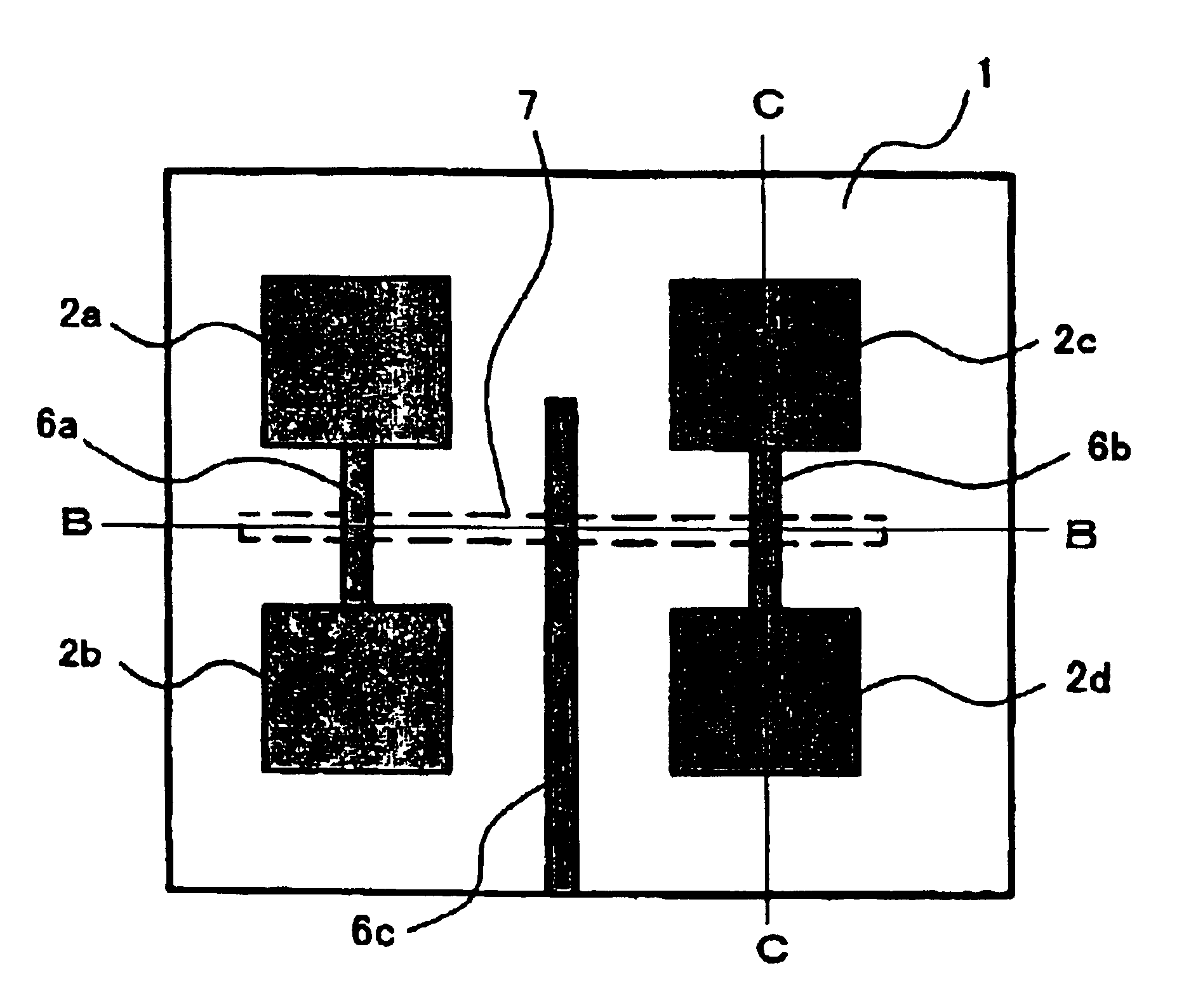
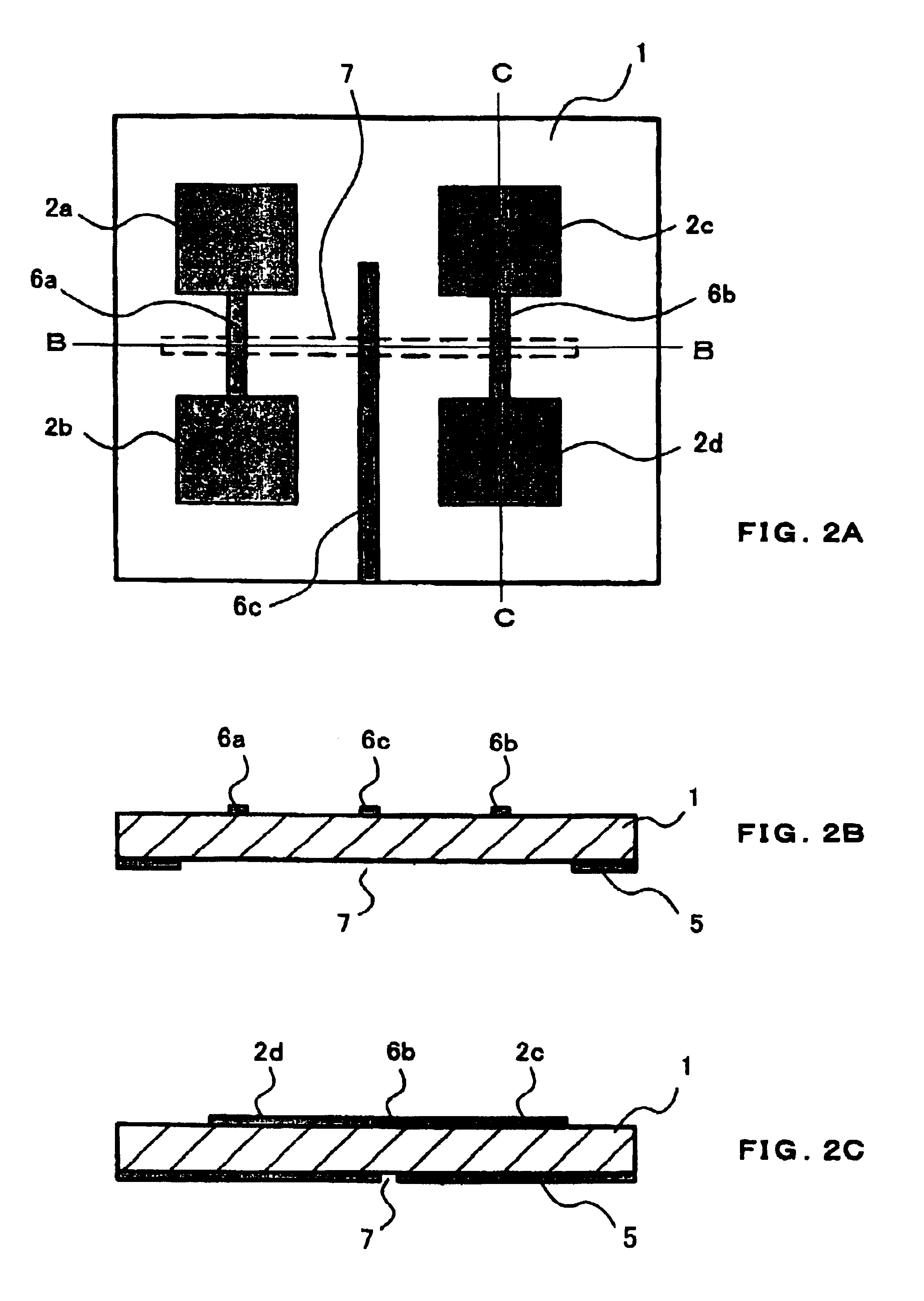
[0029]As shown in FIGS. 2A through 2C, a multielement planar antenna according to the present invention has substrate 1 made of a dielectric material, a matrix of antenna elements each in the form of a microstrip line disposed on one main surface of substrate 1, and grounded metal conductor 5 disposed on and covering substantially entirety the other main surface of substrate 1. In the illustrated embodiment, four substantially rectangular antenna elements 2a through 2d arranged in two rows and two columns are disposed on the one main surface of substrate 1.

[0030]The multielement planar antenna also has first microstrip line 6a disposed on the one main surface of substrate 1 and extending between and joined to confronting sides of antenna elements 2a, 2b which are positioned on a left portion (as shown) of substrate 1, and second microstrip line 6b disposed on the one main surface of substrate 1 and extending between and joined to confronting sides of antenna elements 2c, 2d which ar...

second embodiment

[0038]A multielement planar antenna according to the present invention will be described below with reference to FIGS. 4A and 4B. Those parts shown in FIGS. 4A and 4B which are identical to those shown in FIGS. 2A through 2C are denoted by identical reference characters.

[0039]In the multielement planar antenna according to the first embodiment, slot line 7 is energized by third microstrip line 6c. In the multielement planar antenna according to the third embodiment, however, slot line 7 is energized by a coplanar line or coplanar waveguide disposed on the other main surface of substrate 1. Coplanar line 10 extends from an edge of substrate 1 to slot line 7, is connected to slot line 7, and electromagnetically couples to slot line 7. Coplanar line 10 comprises two narrow parallel grooves 10A defined in metal conductor 10B disposed on the other main surface of substrate 1, with metal conductor 10B between narrow grooves 10A being used as a signal line. Narrow grooves 10A are connected...

third embodiment

[0048]With the above arrangement, the multielement planar antenna has an increased number of antenna elements for increased sensitivity. On this multielement planar antenna, a feeding path is basically made up of a microstrip line / a slot line / microstrip lines / (and slot lines). Stated otherwise, connections, i.e., a feeding structure, are established from a parallel in-phase branched structure to an opposite-phase series branched structure. As with the previous embodiments, therefore, the overall feeding line for energizing the antenna elements has a minimum length, no matching circuit is required, and mutual interference between the feeding lines and the antenna elements is prevented. A transmission / reception module employing the multielement planar antenna may be constructed by surface-mounting a circuit device such as an IC on second slot line 7b.

[0049]In the above planar antenna, the upper and lower sets of antenna elements as shown are connected to each other, and fed, by micr...


PUM


Abstract

A multielement planar antenna has a substrate, a plurality of antenna element pairs disposed on a first main surface of said substrate, each of the antenna element pairs including first and second antenna elements each made of a circuit conductor, a metal conductor disposed on a second main surface of the substrate, and a slot line defined in the metal conductor. Each of the antenna element pairs has a microstrip line interconnecting the first and second antenna elements. The slot line crosses the microstrip lines and is electromagnetically coupled to the microstrip lines for feeding the first and second antenna elements. The slot line is fed at its central area by a microstrip line or a coplanar line.

Description

BACKGROUND OF THE INVENTION[0001]1. Field of the Invention[0002]The present invention relates to a high-frequency multielement array planar antenna, and more particularly to a multielement planar antenna which employs microstrip lines for improved sensitivity and has active devices and integrated circuits (ICs) mounted thereon for use as an active antenna.[0003]2. Description of the Related Art[0004]Planar antennas have widely been used as microwave and millimeter wave antennas in the fields of radio communications and satellite broadcasting applications. Generally, planar antennas include microstrip line antennas and slot line antennas. Of these planar antennas, microstrip line antennas find wider use than slot line antennas because they have a simpler feeder structure and better radiating characteristics. However, since the microstrip line antennas have a low antenna gain, it is customary for them to be constructed as a multielement array antenna having a plurality of antenna elem...

Claims


Application Information

Patent Timeline
Patent Type & Authority Patents(United States)
IPC IPC(8): H01Q9/04H01Q23/00H01Q21/06H01Q21/00H01P5/08H01Q13/08
CPCH01Q9/0457H01Q21/0006H01Q21/065H01Q23/00H01L2223/6627H01L2223/6677H01L2223/6683H01L2224/16225H01L2924/00014H01L2224/0401
Inventor AIKAWA, MASAYOSHINISHIYAMA, EISUKEEGASHIRA, KOZOASAMURA, FUMIOOITA, TAKEO
Owner NIHON DEMPA KOGYO CO LTD
Why Eureka
Try Eureka