Image sensing apparatus, method and recording medium storing program for method of setting plural photographic modes and variable specific region of image sensing, and providing mode specific compression of image data in the specific region

a technology of image sensing apparatus and recording medium, applied in the direction of television system, exposure control, instruments, etc., can solve the problems of time-consuming data transfer or printing operation, inability to record a particular region of an image in higher quality, and large compressed image files, so as to improve flexibility in expression of a sensed image and uniform image quality. , the effect of increasing the flexibility

Inactive Publication Date: 2005-07-12
CANON KK
View PDF19 Cites 49 Cited by
  • Summary
  • Abstract
  • Description
  • Claims
  • Application Information

AI Technical Summary

Benefits of technology

[0012]By virtue of the present invention as described above, the image quality of the entire sensed image can be made uniform, and flexibility in expression of a sensed image is increased.
[0013]It ...

Problems solved by technology

Therefore, it is impossible to record a particular region of an image in higher quality than other regions of the image.
As a result, the size of the compressed image file becomes large, and this causes problems of time-consuming data transfer or printing operation.
Furthermore, when recording time is limited, e.g., at a time of image data transfer or during a continuous...

Method used


Image

  • Image sensing apparatus, method and recording medium storing program for method of setting plural photographic modes and variable specific region of image sensing, and providing mode specific compression of image data in the specific region
  • Image sensing apparatus, method and recording medium storing program for method of setting plural photographic modes and variable specific region of image sensing, and providing mode specific compression of image data in the specific region
  • Image sensing apparatus, method and recording medium storing program for method of setting plural photographic modes and variable specific region of image sensing, and providing mode specific compression of image data in the specific region

Examples


first embodiment

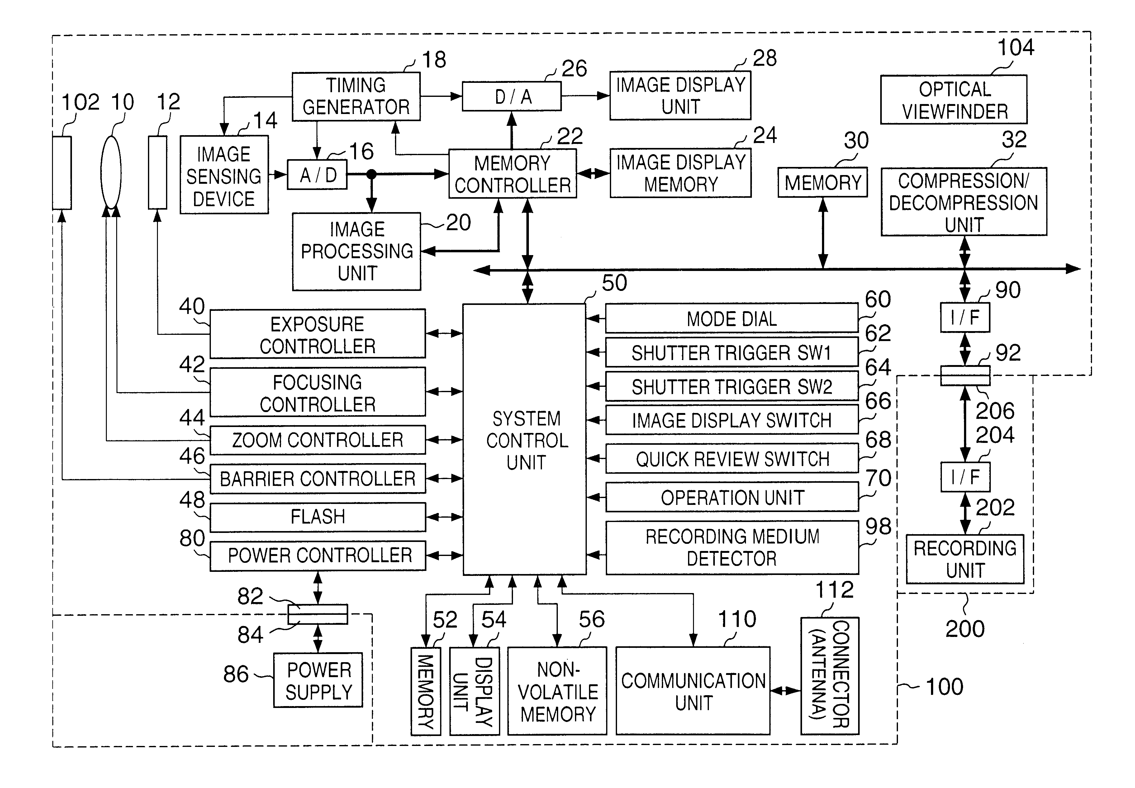
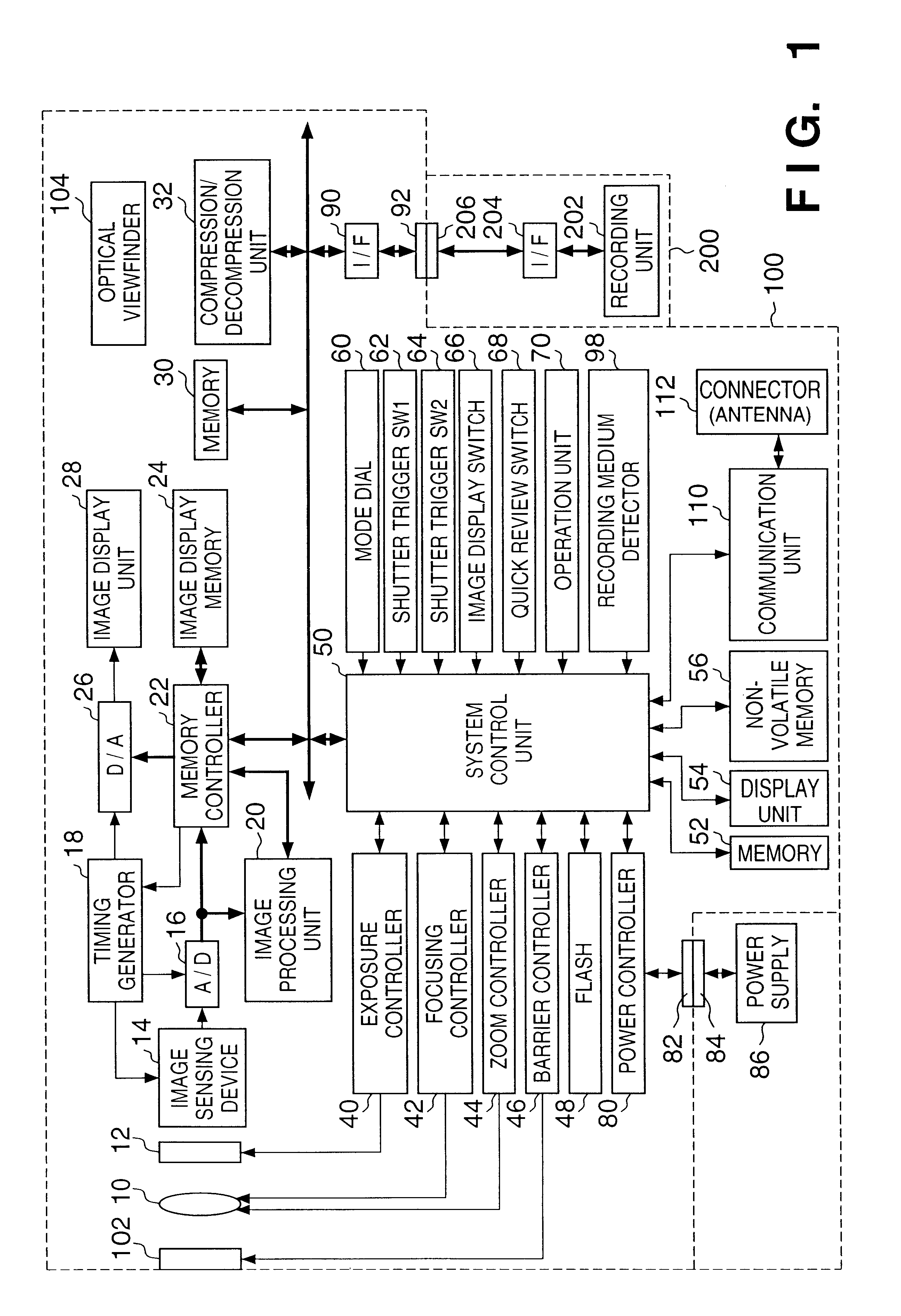
[0035]FIG. 1 is a block diagram showing a construction of an image sensing system according to the Reference numeral 100 denotes an image sensing apparatus, such as a digital camera or the like, and 200 denotes a recording medium, such as a memory card, hard disk or the like.

Construction of Image Sensing Apparatus

[0036]Hereinafter, a construction of the image sensing apparatus 100 is described in detail. Reference numeral 10 denotes a lens; 12, a shutter having a diaphragm function; 14, an image sensing device which converts an optical image to electrical signals; and 16, an A / D converter for converting analog signals output by the image sensing device 14 to digital signals. Reference numeral 18 denotes a timing generator which supplies clock signals or control signals to the image sensing device 14, A / D converter 16, and D / A converter 26, and is controlled by a memory controller 22 and system control unit 50.

[0037]Reference numeral 20 denotes an image processing unit which perform...

second embodiment

[0125]Hereinafter, a second embodiment according to the present invention is described.

[0126]The second embodiment is characterized by making the photographing mode selectable for either designating an ROI mode or not designating an ROI mode. Since the construction of the image sensing apparatus according to the second embodiment is the same as that described in the first embodiment with reference to FIG. 1, hereinafter the same reference numerals as that in FIG. 1 are used and detailed description will not be provided.

[0127]FIGS. 13A and 13B are flowcharts of the main routine according to the second embodiment. In contrast with FIGS. 11A and 11B described in the first embodiment, according to FIGS. 13A and 13B, after a photographing mode is confirmed in step S103 and before the continuous photographing mode is determined in step S107, the ROI mode is confirmed in step S106. Since other steps in FIGS. 13A and 13B are the same as that in FIGS. 11A and 11B, detailed description thereo...

third embodiment

[0131]Hereinafter, a third the third embodiment according to the present invention is described.

[0132]In general, when a sensed image includes a large amount of high-frequency components, the amount of compressed data is larger than that including less amount of high-frequency components. For this reason, data transfer and data writing in a recording medium require a longer time. In other words, image sensing intervals in continuous photographing vary depending on the picture of the sensing image.

[0133]Particularly, when the ROI mode is designated as described in the second embodiment, the total amount of compressed data varies depending on whether or not the image in the set ROI includes a large amount of high-frequency components, and the fluctuation is larger in the case where the ROI mode is designated than the case where the ROI mode is not designated. Therefore, if the ROI mode is designated in the continuous photographing mode, the variation of image sensing intervals becomes...


PUM


Abstract

When a region of interest of an image is compressed with high quality by an image sensing apparatus, such as a digital camera or the like, the region of interest (ROI) can be compressed by a compression coefficient different from that of other regions of the image according to the so-called JPEG 2000 method. However, setting the ROI is a complicated operation for a user. In the present invention, when a continuous photographing mode is not set, a single image sensing operation is assumed and the ROI is automatically set in a first region, which is the largest of three regions. Whereas in the continuous photographing mode, if a low-speed mode is set, the ROI is set in a second region smaller than the first region, and if a high-speed mode is set, the ROI is set in a third region, which is the smallest. In other words, the ROI is automatically set in the largest region in the single photographing mode, and when the continuous photographing mode is set, the ROI is automatically set larger in the low-speed mode than in the high-speed mode.

Description

FIELD OF THE INVENTION[0001]The present invention relates to an image sensing apparatus and control method thereof, and more particularly, to an image sensing apparatus for compressing sensed images and storing the compressed images, and to a control method thereof.BACKGROUND OF THE INVENTION[0002]Image sensing apparatuses, e.g., conventional digital cameras or the like, which sense, record and reproduce an image, often employ a data compression technique complying with the JPEG baseline scheme.[0003]However, the conventional JPEG baseline scheme utilizes one quantization table for the entire image on a screen. Therefore, it is impossible to record a particular region of an image in higher quality than other regions of the image. If a user desires higher image quality for a particular region of the image, other regions must also be compressed as a high-quality image. As a result, the size of the compressed image file becomes large, and this causes problems of time-consuming data tra...

Claims


Application Information

Patent Timeline
IPC IPC(8): H04N7/24H04N5/225H04N5/222H04N1/333H04N5/235H04N19/00H04N19/115H04N19/12H04N19/134H04N19/167H04N19/184
CPCH04N1/215H04N1/3333H04N5/2352H04N19/63H04N19/17H04N19/42H04N2101/00H04N2201/33357H04N23/72
Inventor FUKUSHIMA, NOBUO
Owner CANON KK
Why Eureka
Try Eureka