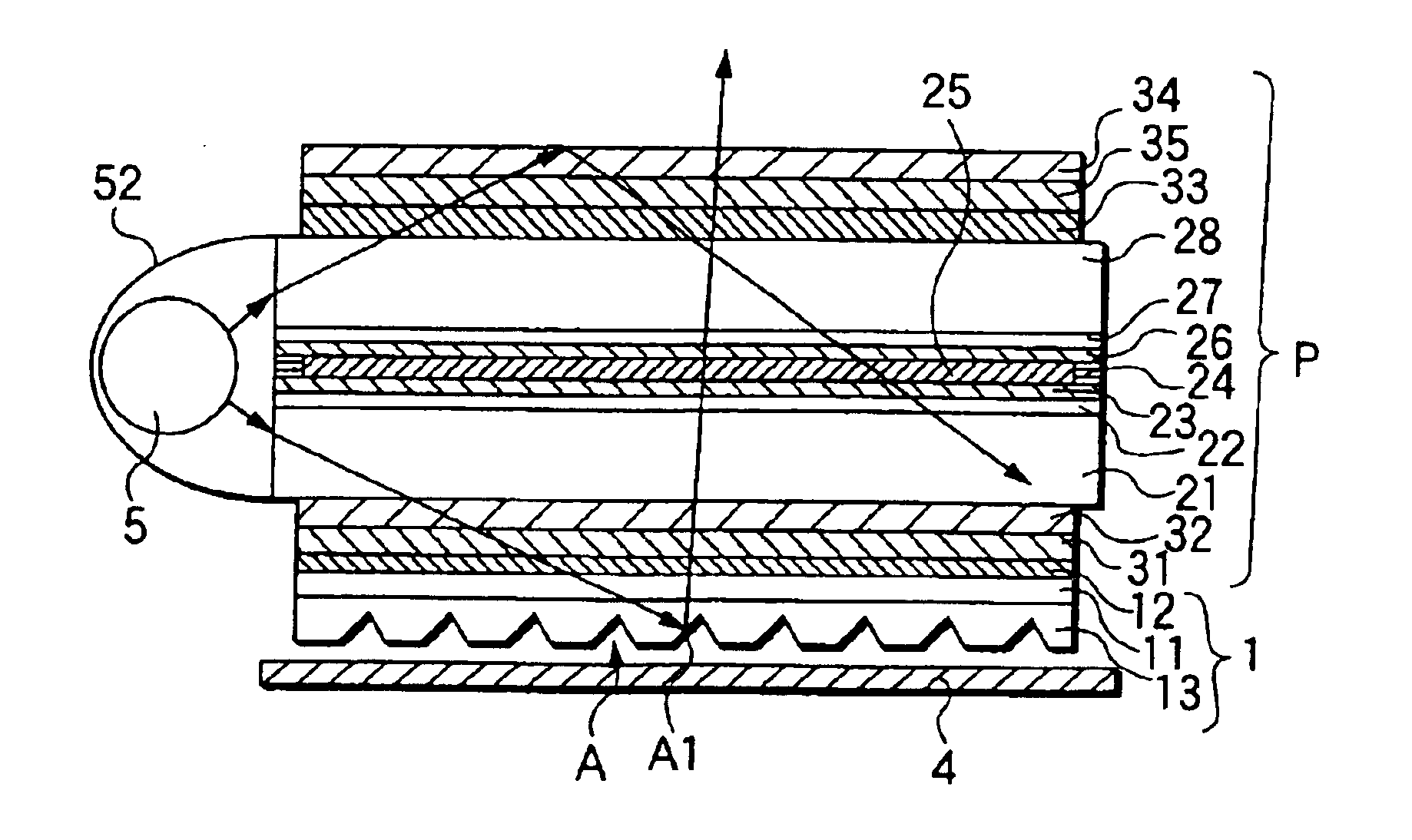
Optical film and liquid-crystal display device
a liquid crystal display device and optical film technology, applied in the direction of instruments, mechanical equipment, lighting and heating apparatus, etc., can solve the problems of difficult to reduce the thickness, size and weight of a transmission the volume and weight of the liquid crystal display device is large, and the liquid crystal display device substantially hardly functions as a reflection type liquid crystal display device, etc., to achieve the effect of ensuring efficient entrance, reflection and transmission of external light, and avoiding the display of can
- Summary
- Abstract
- Description
- Claims
- Application Information
AI Technical Summary
Benefits of technology
Problems solved by technology
Method used
Image
Examples
example 1
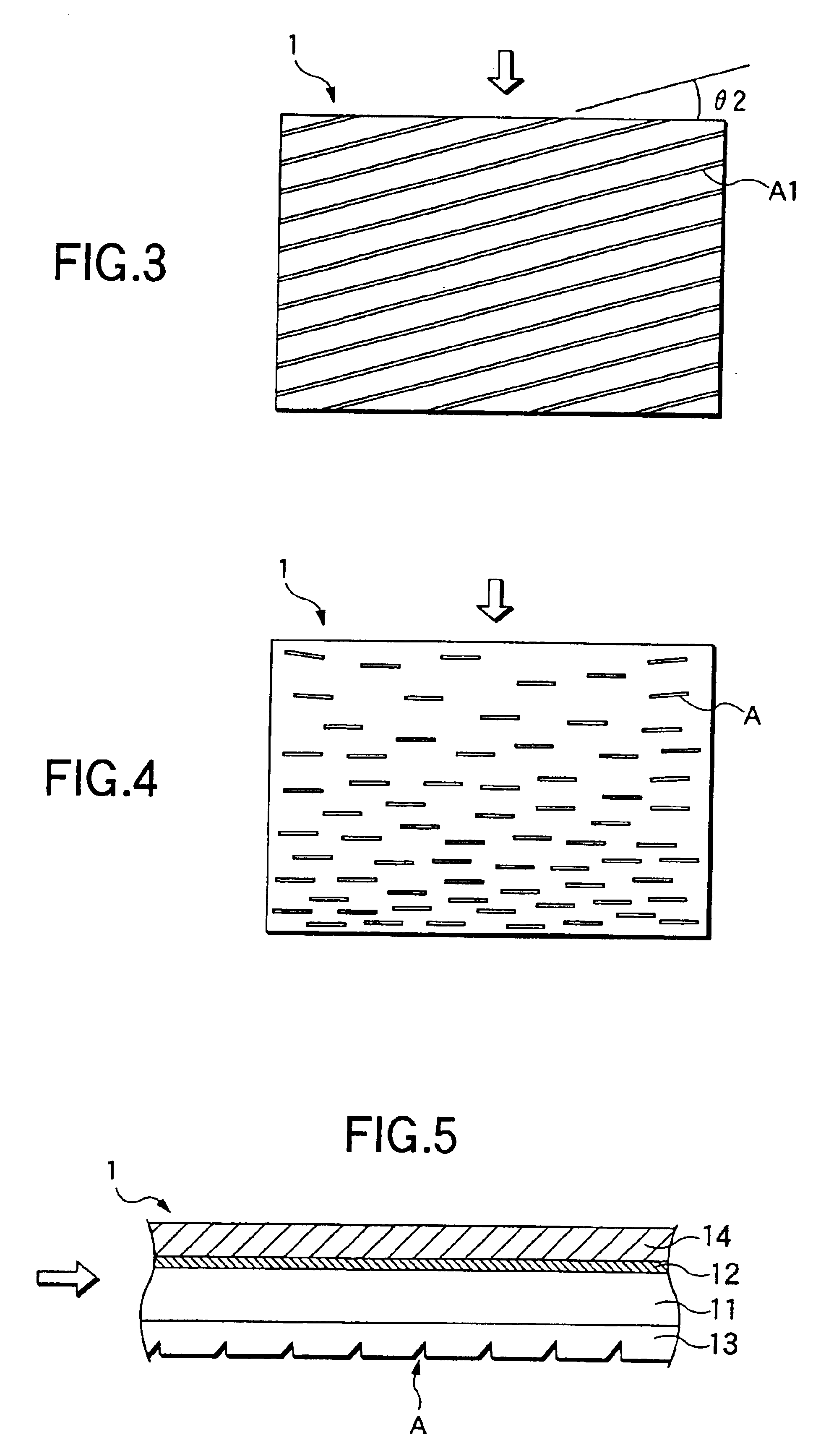
[0093]A mold processed into a predetermined shape in advance was filled with acrylic ultraviolet-curable resin (ARONIX UV-3701, made by TOAGOSEI Co., Ltd.) by dropping with a dropper. An 80 μm-thick triacetylcellulose (TAC) film (having a saponified surface) was disposed quietly on the resin, and made to adhere closely to the resin by a rubber roller so as to eliminate excessive resin and bubbles. The TAC film with the resin was irradiated with ultraviolet rays by a metal halide lamp so as to be cured. The resin-including TAC film cured thus was stripped off from the mold and cut into a predetermined size. Thus, a transparent film was obtained so that a layer of a plurality of optical path changing means having a refractive index of 1.533 was formed on the TAC film having a refractive index of 1.49. Then, a tacky layer with a refractive index of 1.47 was provided on the other surface of the transparent film on which the plurality of optical path changing means were not formed. Thus,...
example 2
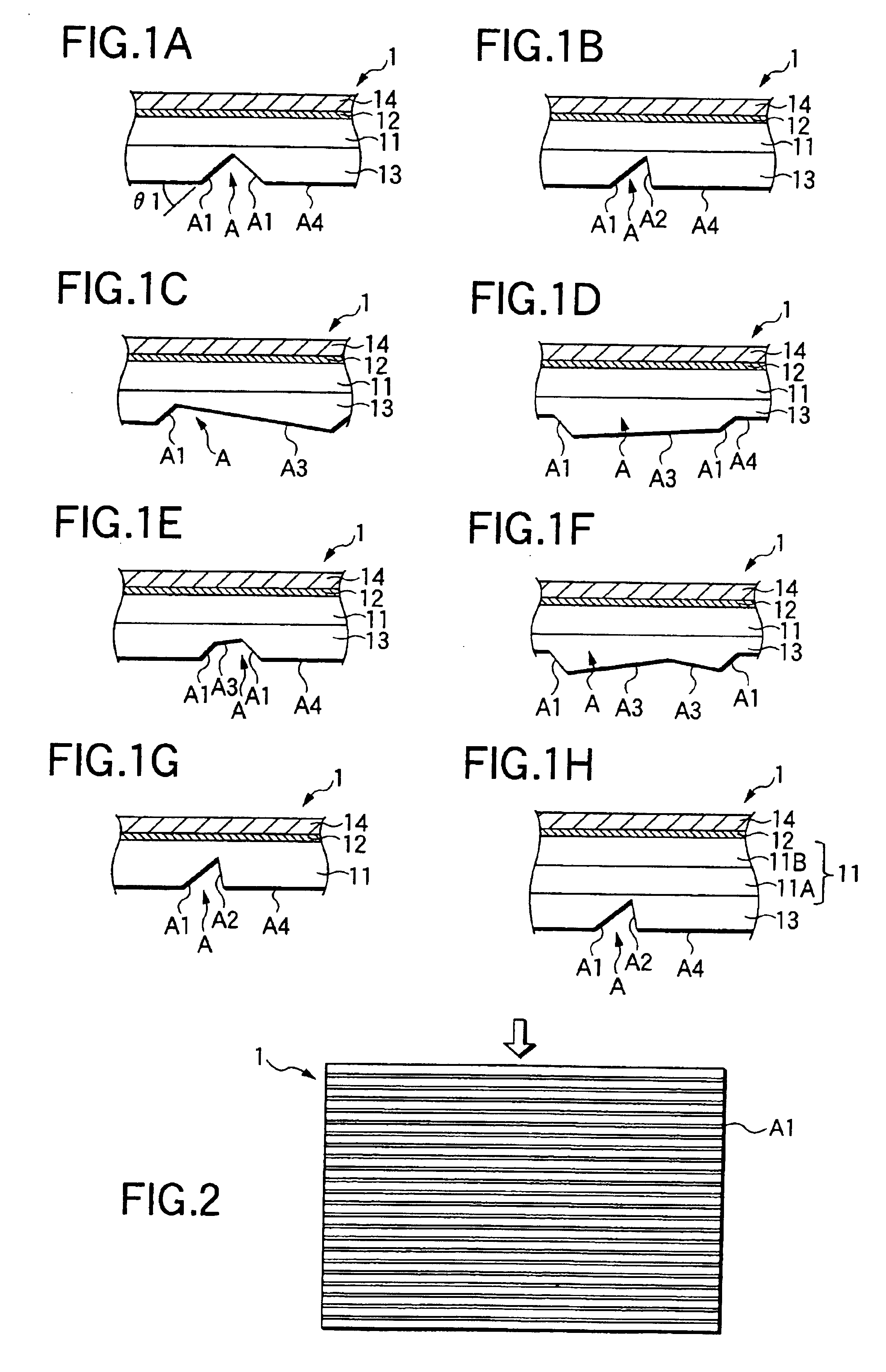
[0096]A transmission type liquid-crystal display-device was obtained by using an optical film in the manner similar to that in Example 1, except that the optical film was formed to have a plurality of optical path changing means (FIG. 1B) each of which had an optical path changing slope A1 inclined at an angle of about 42 degrees, a steep slope A2 having a vertex angle of 70 degrees with the optical path changing slope A1, and a flat surface A4 having a projected area not smaller than 10 times as large as the total projected area of the optical path changing slope A1 and the steep slope A2 on the film plane.
example 3
[0097]A transmission type liquid-crystal display device was obtained by using an optical film (FIG. 6) in the manner similar to that in Example 1, except that the optical film was formed to have a plurality of optical path changing means each having a length of 80 μm (FIG. 1B). Each of the plurality of optical path changing means had an optical path changing slope A1 which had an inclination angle of about 42 degrees and which had a projected width of 10 μm on the film plane, and a steep slope A2 which had an inclination angle of about 55 degrees. The plurality of optical path changing means were disposed so that the lengths of the plurality of optical path changing means were substantially parallel with one another in the widthwise direction of the optical film, and so that the density of the optical path changing means became gradually higher as the location went farther from the side surface, on which the light is incident, in the widthwise direction of the optical film. Incident...
PUM
| Property | Measurement | Unit |
|---|---|---|
| thickness | aaaaa | aaaaa |
| refractive index | aaaaa | aaaaa |
| inclination angle | aaaaa | aaaaa |
Abstract
Description
Claims
Application Information
 - R&D
- Intellectual Property
- Life Sciences
- Materials
- Tech Scout
- Unparalleled Data Quality
- Higher Quality Content
- 60% Fewer Hallucinations
Browse by: Latest US Patents, China's latest patents, Technical Efficacy Thesaurus, Application Domain, Technology Topic, Popular Technical Reports.
© 2025 PatSnap. All rights reserved.Legal|Privacy policy|Modern Slavery Act Transparency Statement|Sitemap|About US| Contact US: help@patsnap.com


