

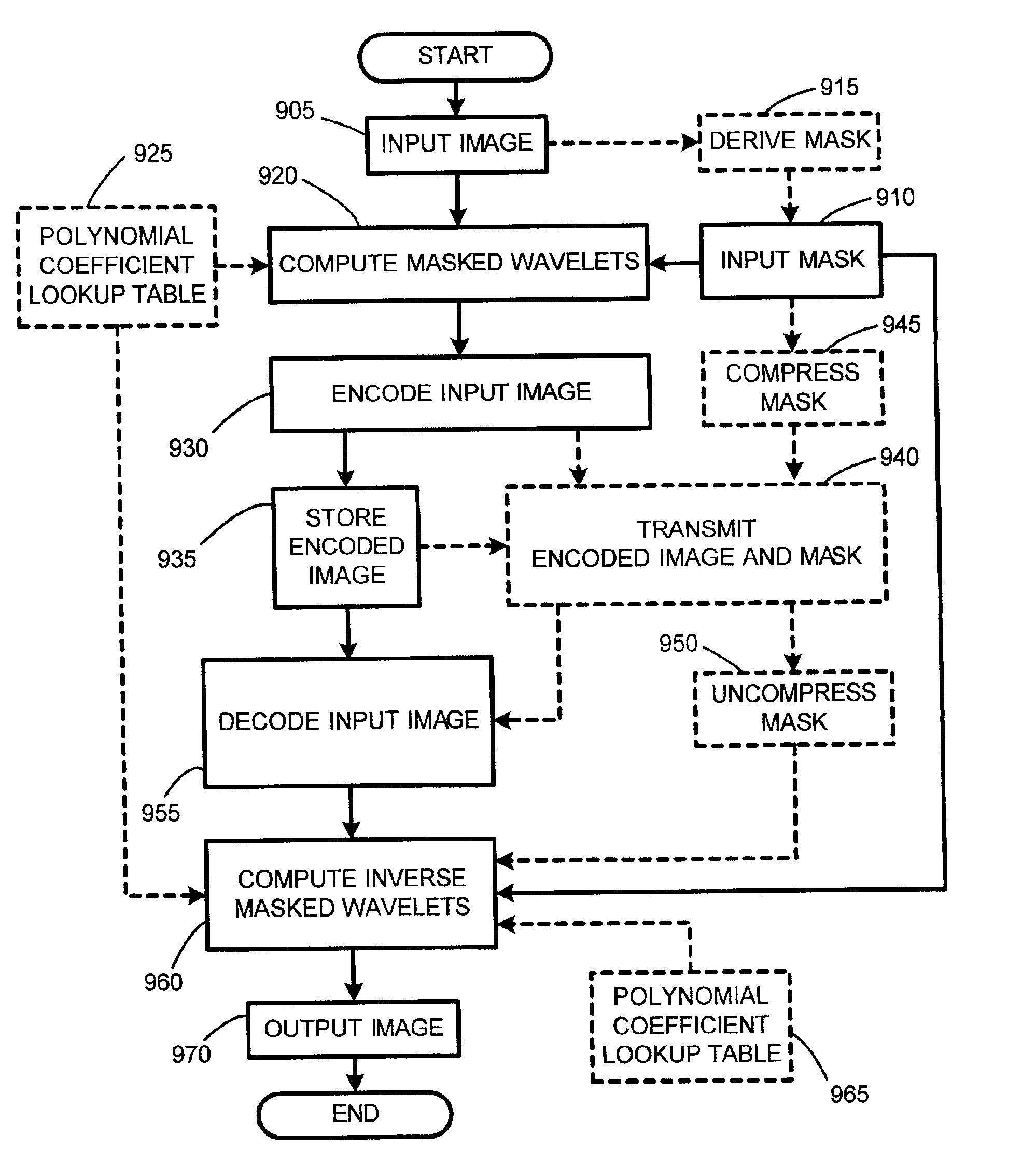
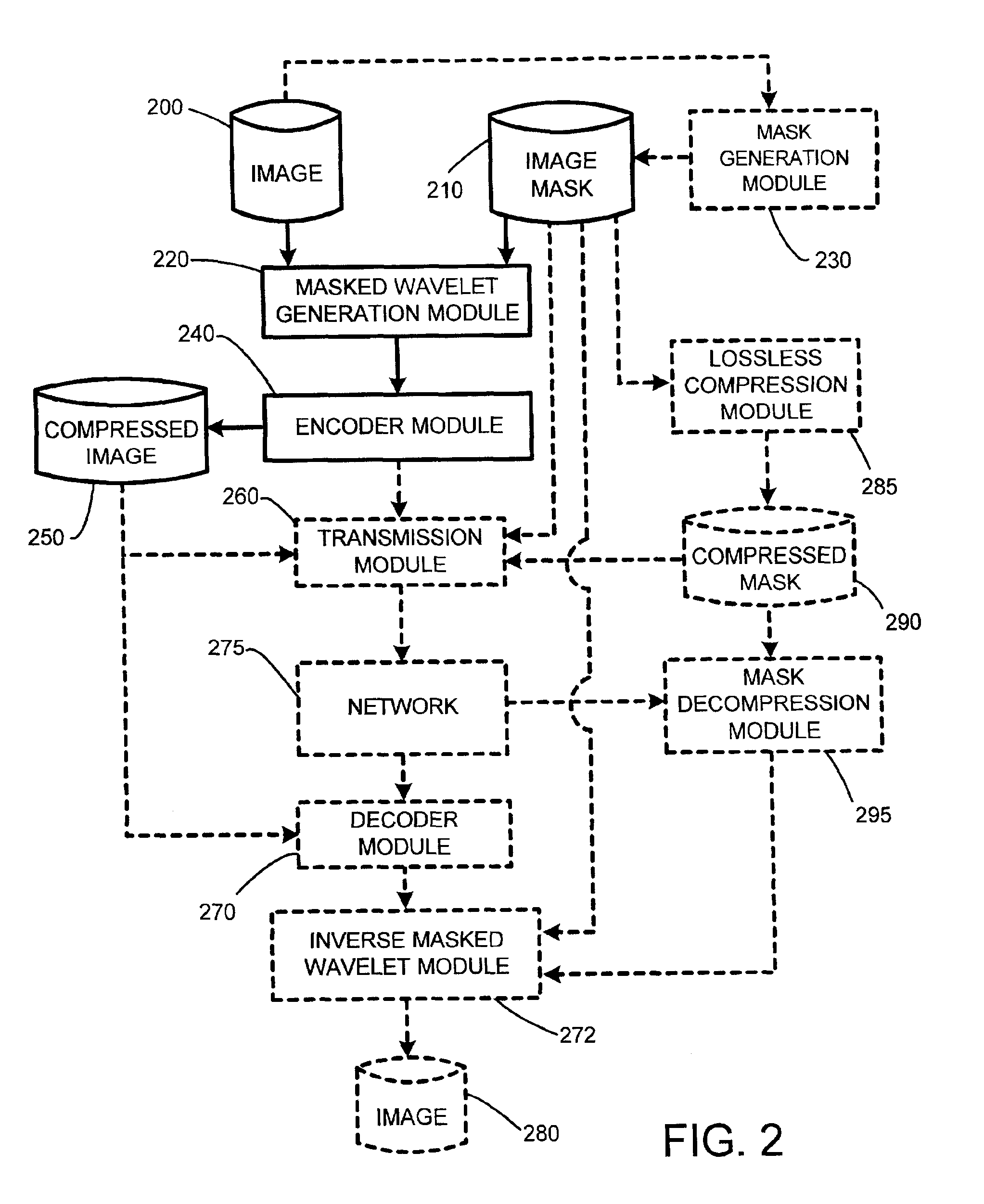
System and method for image compression using wavelet coding of masked images
a wavelet coding and image compression technology, applied in the field of image compression system, can solve the problems of increasing the required bit rate, affecting the efficiency of filling schemes based on such filling techniques, and achieving poor compression of composite images by existing image compression schemes
- Summary
- Abstract
- Description
- Claims
- Application Information
AI Technical Summary
Benefits of technology
Problems solved by technology
Method used
Image

Examples
Embodiment Construction
[0030]In the following description of the preferred embodiments of the present invention, reference is made to the accompanying drawings, which form a part hereof, and in which is shown by way of illustration specific embodiments in which the invention may be practiced. It is understood that other embodiments may be utilized and structural changes may be made without departing from the scope of the present invention.
1.0 Exemplary Operating Environment:
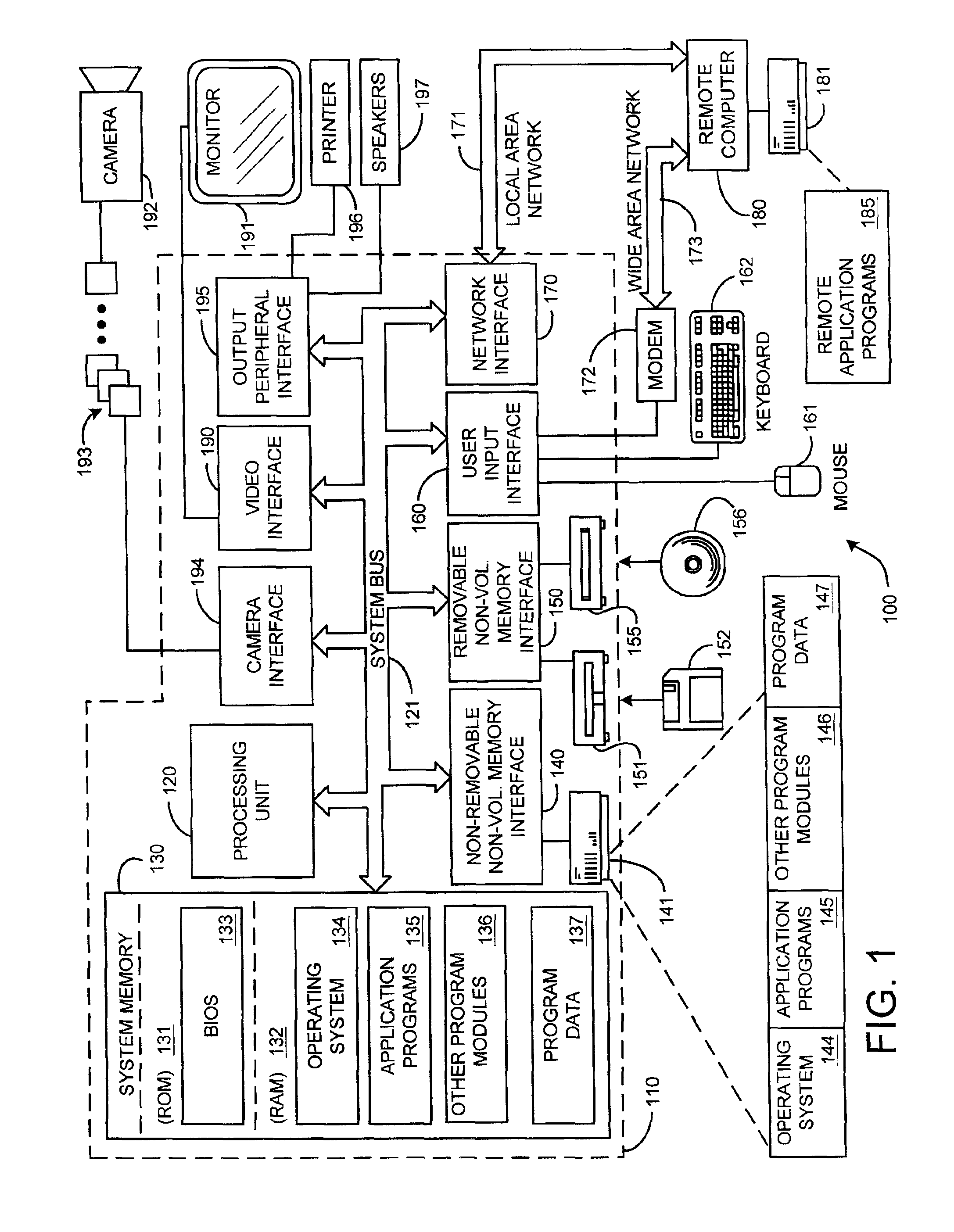
[0031]FIG. 1 illustrates an example of a suitable computing system environment 100 on which the invention may be implemented. The computing system environment 100 is only one example of a suitable computing environment and is not intended to suggest any limitation as to the scope of use or functionality of the invention. Neither should the computing environment 100 be interpreted as having any dependency or requirement relating to any one or combination of components illustrated in the exemplary operating environment 100.
[0032]The inve...
PUM
 Abstract
Description
Claims
Application Information