Optical cache memory

a cache memory and optical data technology, applied in logic circuits, pulse techniques, instruments, etc., can solve the problems of high data rate, complex circuitry, and inability to operate at high data ra

Inactive Publication Date: 2005-07-12
AVAGO TECH WIRELESS IP SINGAPORE PTE
View PDF15 Cites 42 Cited by
  • Summary
  • Abstract
  • Description
  • Claims
  • Application Information

AI Technical Summary

Problems solved by technology

While optical communication channels provide data rates in excess of 10 Gbits/sec at relatively modest costs, electrically base...

Method used


Image

  • Optical cache memory
  • Optical cache memory
  • Optical cache memory

Examples


Embodiment Construction

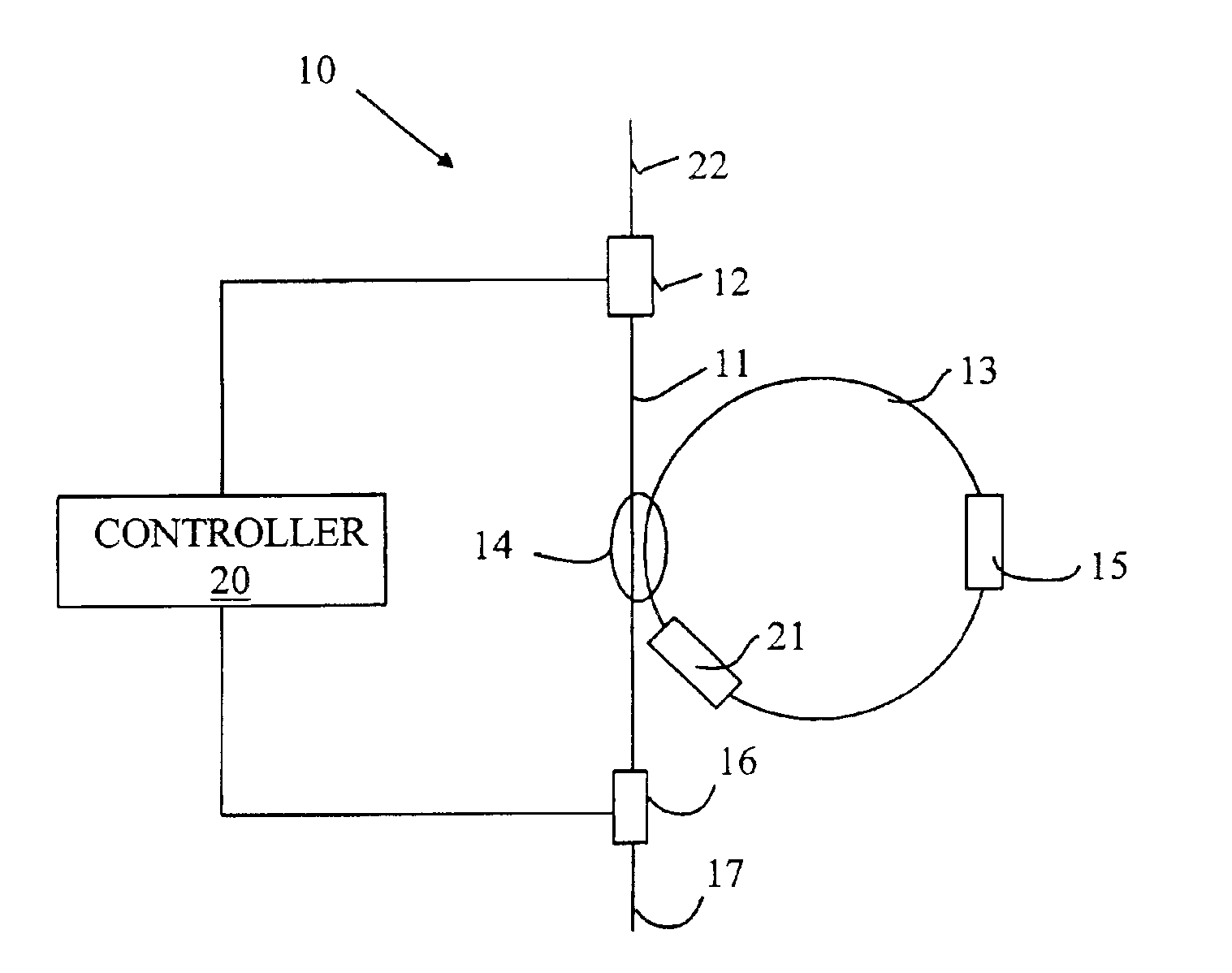
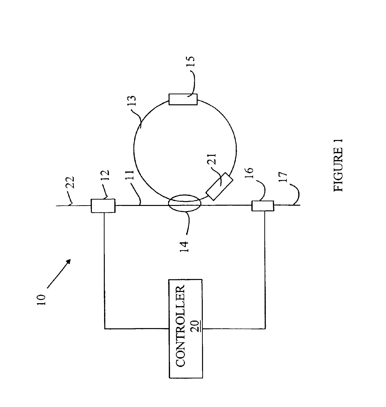
[0014]The present invention avoids the costly circuitry discussed above by providing an optically based cache for storing optical data packets. The manner in which the present invention stores an optical signal can be more easily understood with reference to FIG. 1, which is a schematic drawing of an optical cache memory 10 according to one embodiment of the present invention. Optical cache memory 10 stores and retrieves optical packets in the form of a modulated optical signal that specifies a plurality of bits of data. Any appropriate form of optical modulation can be utilized including amplitude modulation, phase modulation, and polarization modulation. An optical packet that is to be stored in optical cache memory 10 is input to optical cache memory 10 on optical fiber 22 through optical switch 12. A portion of the light traversing optical fiber 11 is diverted into storage loop 13 by coupler 14. Each time the optical packet traverses storage loop 13, a portion of the circulating...


PUM


Abstract

An optical memory having an input port for receiving an input optical signal to be stored in the optical memory is disclosed. A portion of the optical signal is coupled to a storage loop for storing optical signals by a coupler that transfers a portion of the input optical signal to the storage loop. An optical signal stored in the storage loop is output by coupling a portion of that optical signal to a first external optical waveguide. The storage loop includes a semiconductor optical amplifier for amplifying the signals stored in the storage loop to compensate for losses incurred by those signals in traversing the storage loop. A plurality of such optical memories can be combined to form a larger memory that includes a reconditioning circuit that resets the amplitude of the optical signals to a value that depends on the amplitude of the optical signals.

Description

FIELD OF THE INVENTION[0001]The present invention relates to storage systems for optical data.BACKGROUND OF THE INVENTION[0002]To simplify the following discussion, the present invention will be explained utilizing optically-based communication systems. However, the present invention can also be utilized in a wide range of other applications as will be discussed in more detail below.[0003]The ever-increasing bandwidth requirements of communication systems have resulted in data being transmitted over optical fibers. Both conventional telecommunications and data networks such as the Internet utilize optical fibers for long distance transmission. Data is sent by breaking the transmission into data packets that are routed between the sender and receiver with the aid of switches that route packets between fibers and / or channels within a single fiber.[0004]While the transmission of the data is performed optically, the switching of the data must often be performed by converting the optical...

Claims


Application Information

Patent Timeline
IPC IPC(8): H04Q11/00G02B6/28G02F3/00G06E3/00G11C21/00H04B10/524H04B10/532H04B10/54H04B10/556H04B10/58
CPCG06E3/00H04Q11/0005G02B6/2861H04Q2011/002
Inventor CHEN, DATONG
Owner AVAGO TECH WIRELESS IP SINGAPORE PTE
Why Eureka
Try Eureka