
Motion data command system and control signal definition system for motion program

a technology of motion data and command system, applied in the field of numerical controllers, can solve the problems of difficult handling of motion program, inability to select control signals individually, etc., and achieve the effect of ensuring operation

Inactive Publication Date: 2005-07-12
YASKAWA DENKI KK
View PDF3 Cites 9 Cited by
  • Summary
  • Abstract
  • Description
  • Claims
  • Application Information

AI Technical Summary

Benefits of technology

The invention aims to provide a system with a simple and easy-to-use preparatory stage that allows for quick changes in motion operation. The system stores variables representing speeds and positions in a memory and allows for quick changes in motion operation by changing the values of these variables. Additionally, the invention provides an API for defining the control signal for activating and terminating a motion program, eliminating the need for a separate tool. This simplifies the operation of a multi-series motion program.

Problems solved by technology

Thus a control signal cannot be selected individually.
Another problem is that, on top of cumbersome definition of an I / O for the control signal, operation of a multi-series motion programs requires definition of the I / O for the control signal for each series as well as definition on which series the motion program belongs to.
This complicates the preparatory stage of a motion program, thus turning the motion program hard to handle.

Method used


Image

  • Motion data command system and control signal definition system for motion program
  • Motion data command system and control signal definition system for motion program
  • Motion data command system and control signal definition system for motion program

Examples


first embodiment

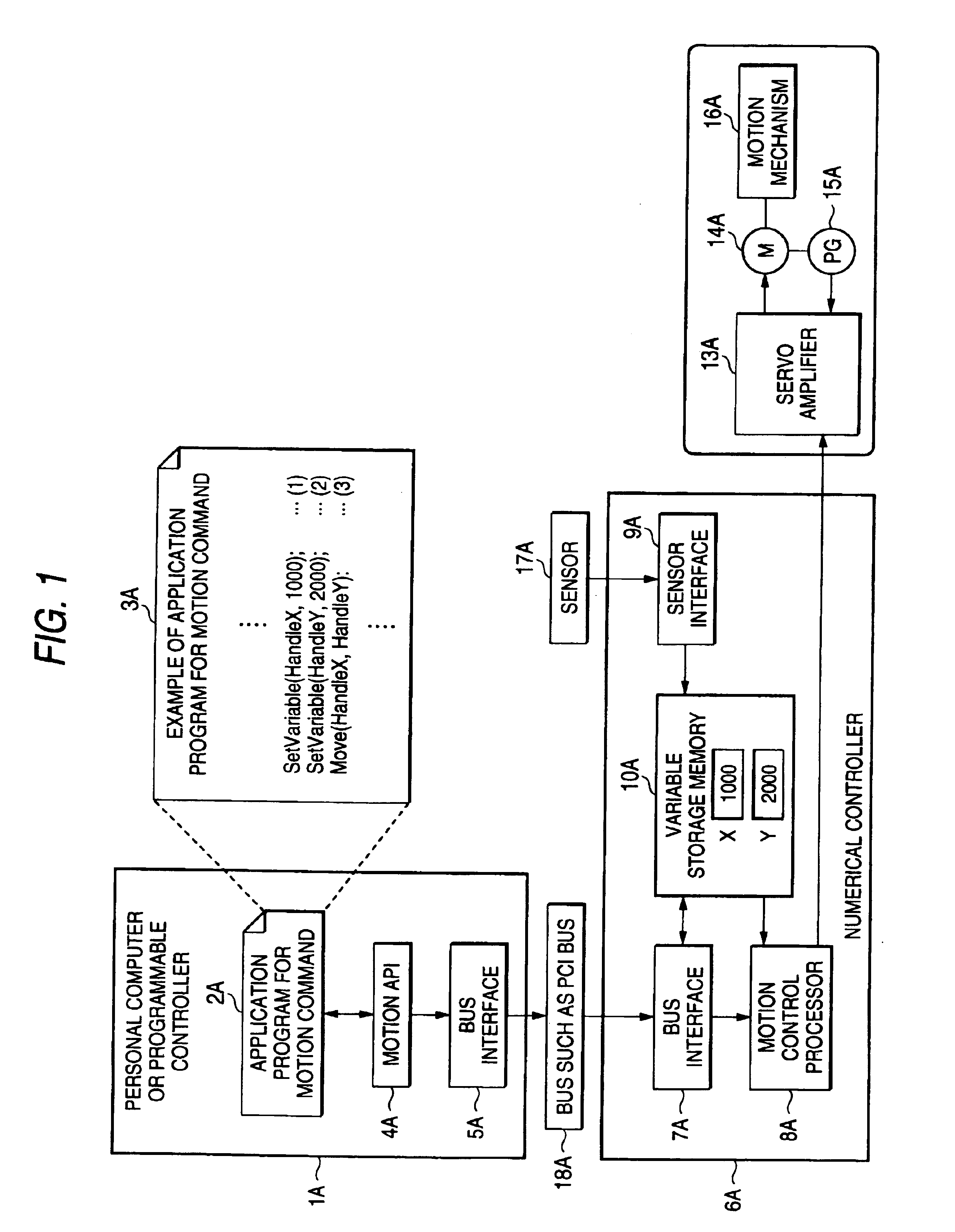
[0021]Embodiments of the invention will be described based on drawings. FIG. 1 is a block diagram of a system which executes a motion data command method according to the invention. In the figure, a numeral 1A represents a personal computer or programmable controller, 2Aan application program for a motion command operating on the personal computer or programmable controller 1A, 3A a specific example of an application program for a motion command, 4A a motion API called by the application program 2A, 5A and 7A bus interfaces for accessing a bus 18A such as a PCI bus, 6A a numerical controller, 8A a motion control processor operating in accordance with given motion command data, 9A a sensor interface for input from a sensor 17A, 10A a variable storage memory for storing motion command data, 13A a servo amplifier, 14A a servo motor, 15A an encoder, and 16A a motion mechanism.

[0022]In the specific example 3A of the application program 2A in FIG. 1, in steps (1) and (2), the initial valu...

second embodiment

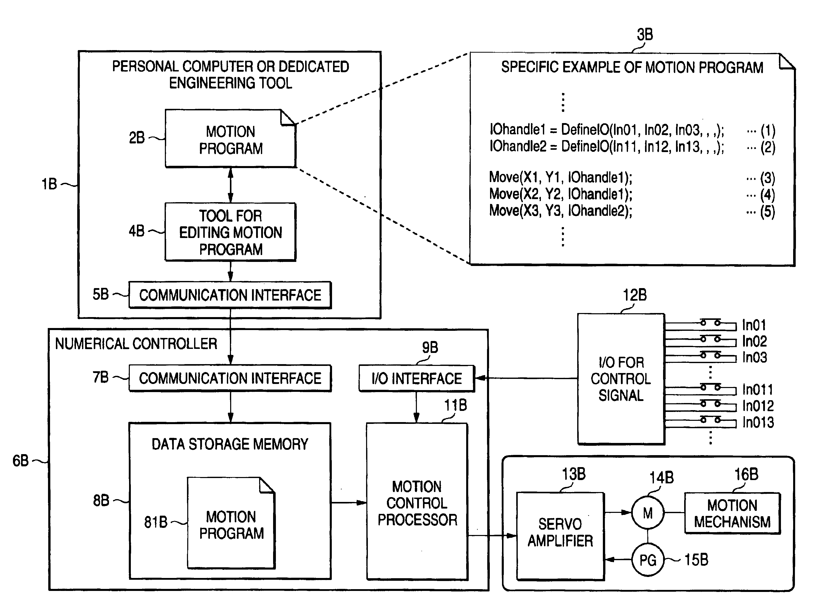
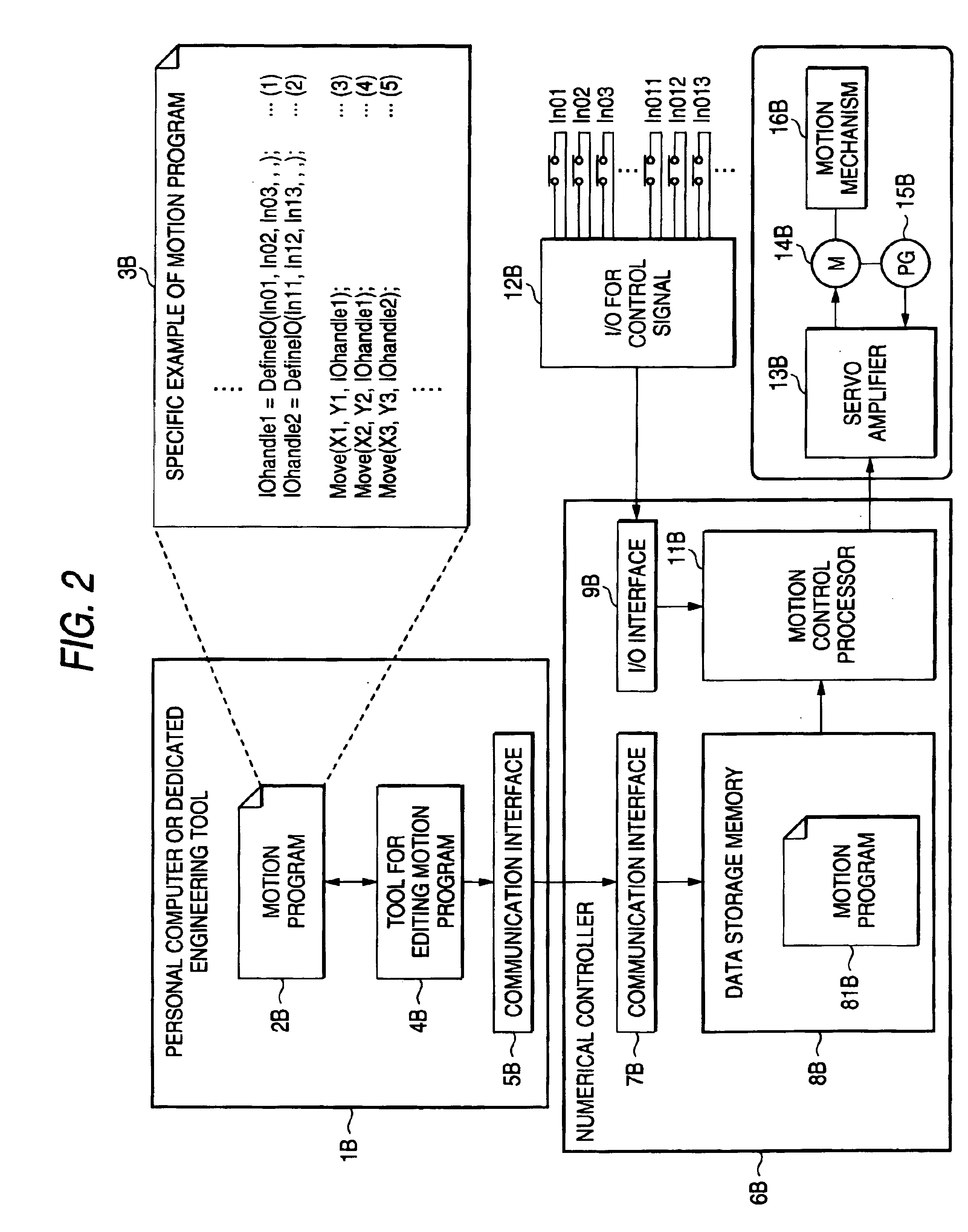
[0026]the invention will be described based on drawings. FIG. 2 is a block diagram of a system which executes a control signal definition method in the motion program according to the invention. In the figure, a numeral 1B represents a personal computer or dedicated engineering tool, 2B a motion program under editing, 3B a specific example of a motion program, 4B a tool for editing the motion program 2B, 5B and 7B communications interfaces for downloading data from a personal computer or dedicated engineering tool 1B to a numerical controller 6B, 8B a data storage memory, 81B a data storage motion program, 9B an I / O interface for input / output of an I / O signal, 12B an I / O for the control signal, 11B a motion control processor operating in accordance with the given motion program 2B, 13B a servo amplifier, 14B a servo motor, 15B an encoder, and 16B a motion mechanism.

[0027]According to one specific example 3B of the application program 2B in FIG. 2, in step (1), an API whose arguments...


PUM


Abstract

A motion data command system for a motion program having a numerical controller for controlling a servo amplifier in accordance with a given motion command. A memory is provided in the numerical controller for storing as variables motion command data. A motion API called by an application program on a personal computer is provided which gives a motion command via a bus to the numerical controller; and indirectly specifying the address of a variable of motion command data present in the memory by way of said motion API.

Description

BACKGROUND OF THE INVENTION[0001]The present invention relates to a numerical controller used to control a machine tool, automatic assembly apparatus and an automatic carrier, and in particular to a method for executing a motion program assumed when the execution environment for the motion program is located outside the numerical controller, such as an a personal computer or a programmable controller.[0002]The invention also relates to a numerical controller used to control a machine tool, automatic assembly apparatus and an automatic carrier, and in particular to a method for defining a control signal for controlling activation / termination of a motion program.[0003]For a conventional art numerical controller whose motion program execution environment exists externally, in case motion command data used for the motion program is a variable, the location of the variable is the location where the execution environment for the motion program exists, that is, in an application program in...

Claims


Application Information

Patent Timeline
Patent Type & Authority Patents(United States)
IPC IPC(8): G05B19/414G06F19/00
CPCG05B19/414G05B2219/34071G05B2219/34208G05B2219/34256G05B2219/34282
Inventor KAMISHIO, TOMOHIRO
Owner YASKAWA DENKI KK
Learn More