Control of multiple supercharged compression ignition engines having EGR

a technology of compression ignition and supercharged engines, applied in the direction of electrical control, process and machine control, instruments, etc., can solve the problems of reducing engine performance, reducing engine speed and load, and reducing engine performance of overpowered turbochargers

Inactive Publication Date: 2005-07-12
NISSAN MOTOR CO LTD
View PDF17 Cites 45 Cited by
  • Summary
  • Abstract
  • Description
  • Claims
  • Application Information

AI Technical Summary

Benefits of technology

[0022]In one exemplary implementation of the present invention, there is provided a system for controlling a vehicle having a compression ignition internal combustion engine, the compression ignition internal combustion engine having an intake manifold, an exhaust gas recirculation (EGR) system and a supercharger system including a plurality of superchargers. The system comprises control logic for determining a desired intake manifold supercharging state and control logic for determining a desired EGR rate. The system also com

Problems solved by technology

Conversely, it operates less efficiently at engine speed and loads for which it is not designed.
As the engine accelerates from idle or slow speeds, there is a delay from the time when the engine load increases to the time when there is sufficient exhaust gas pressure to spin the turbine.
Even when the turbine spins, the exhaust gas pressure may not reac

Method used


Image

  • Control of multiple supercharged compression ignition engines having EGR
  • Control of multiple supercharged compression ignition engines having EGR
  • Control of multiple supercharged compression ignition engines having EGR

Examples


Embodiment Construction

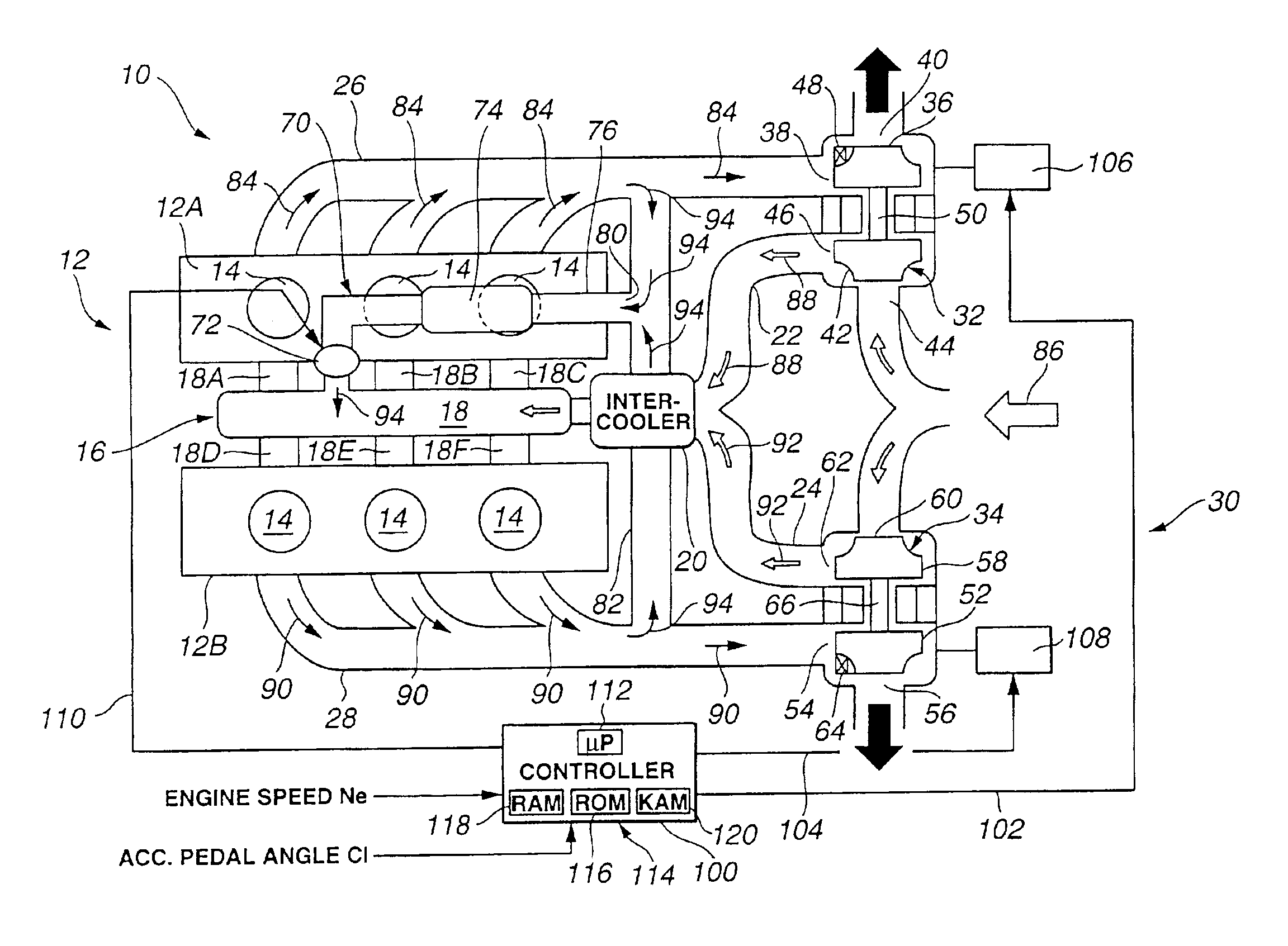
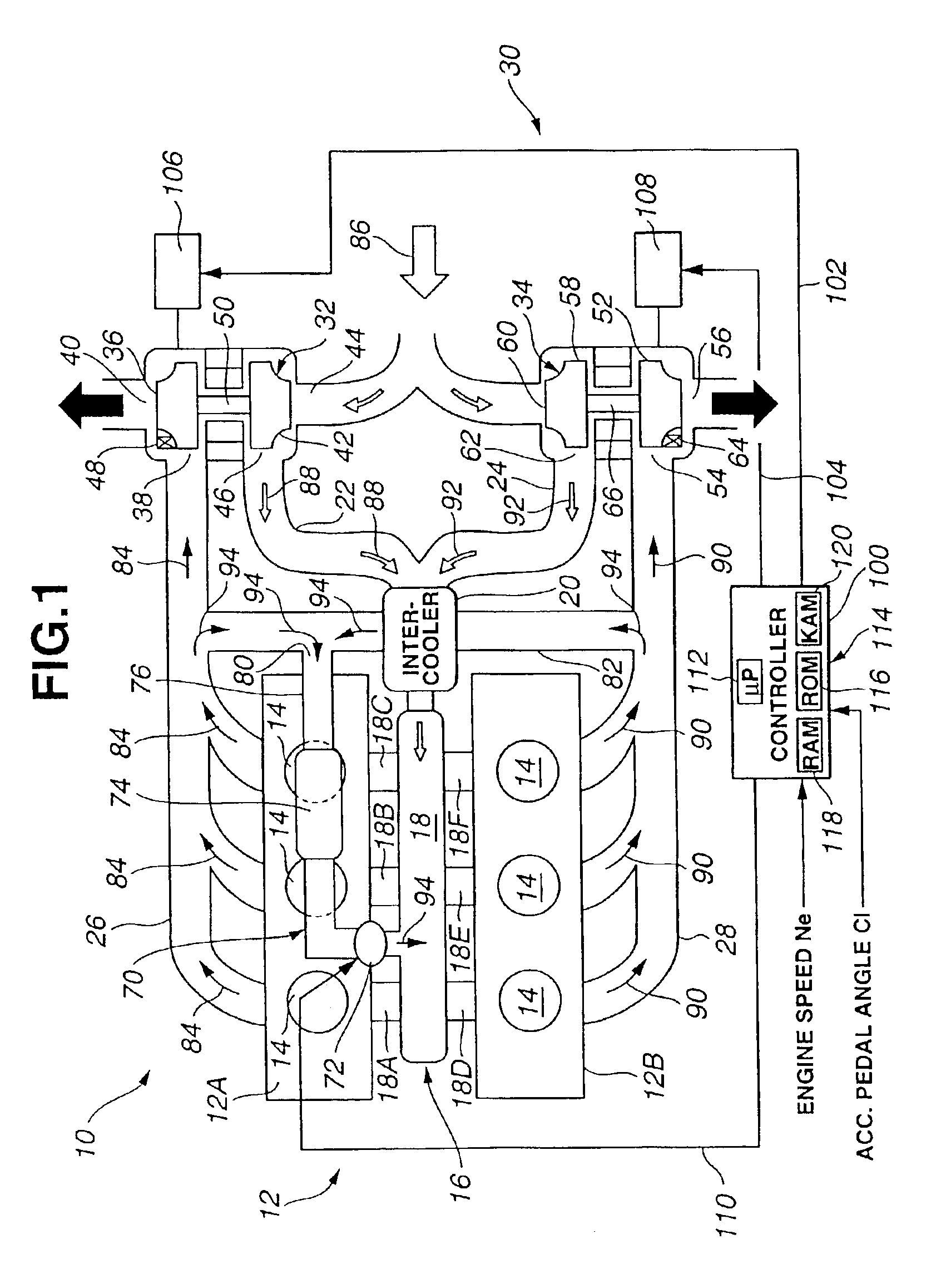
[0046]Referring first to FIG. 1, there is shown a schematic view of a system for controlling a vehicle. The system, generally indicated by reference numeral 10, includes an internal combustion engine 12 having a plurality of combustion cylinders 14, each fed by a fuel injector, not shown. In an exemplary embodiment, engine 12 is a compression ignition internal combustion engine, such as a six, eight or twelve-cylinder diesel engine or a diesel engine having any desired number of combustion cylinders. The fuel injectors receive pressurized fuel from a supply connected to one or more high or low pressure pumps (not shown) as is well known in the art. Engine 12 has a V-configuration or an in-line configuration, and in embodiment shown in FIG. 1 has a V-configuration. In FIG. 1, engine 12 has six combustion cylinders 14, three in a first bank 12A of the V-configuration and the remaining three in a second bank 12B thereof.

[0047]Each of combustion cylinders 14 is coupled with a correspond...


PUM


Abstract

A vehicle system controls a compression ignition internal combustion engine equipped with a supercharger system including a plurality of superchargers. The compression ignition internal combustion engine has an exhaust gas recirculation (EGR) system. The vehicle system determines a desired intake manifold supercharging state (tQac) and a desired EGR rate (Megr). The vehicle system includes control logics, each having a first input parameter and a second input parameter, for determining desired set points (Rvnt1 & Rvnt2) for the plurality of superchargers, respectively. The desired set points are used to control the plurality of superchargers, respectively. The vehicle system also includes control logic for determining the first input parameters in response to the desired intake manifold supercharging state. The vehicle system further includes control logic for determining the second input parameters in response to the desired EGR rate.

Description

BACKGROUND OF THE INVENTION[0001]1. Field of the Invention[0002]The present invention relates generally to supercharged compression ignition engines having an exhaust gas recirculation (EGR) and, more particularly, to a system for and a method of controlling a compression ignition internal combustion engine having an EGR system and a multiple supercharger system including a plurality of superchargers.[0003]2. Description of the Background Art[0004]Many compression ignition engines use turbochargers to improve engine performance. A turbocharger increases the density of the intake air into the engine. The higher density air increases the amount of fuel the engine may combust. As a result, the power output of the engine increases.[0005]Turbochargers typically include a turbine and a compressor connected by a common shaft. The turbine has blades attached to a wheel, which is mounted on the shaft. A turbine housing encloses the turbine and connects to the exhaust manifold of the engine. ...

Claims


Application Information

Patent Timeline
IPC IPC(8): F02D21/00F02D41/00F02D21/08F02B37/24F02M25/07F02B37/007F02B37/12F02B37/00F02B37/18F02B39/16F02D23/00F02D23/02
CPCF02B37/007F02B37/24F02D41/0072F02M25/0711F02M25/0749F01N13/107F02B29/0406F02M25/0727F02M25/0738Y02T10/144Y02T10/47F02M26/08F02M26/23F02M26/33F02M26/43Y02T10/12Y02T10/40
Inventor ITOYAMA, HIROYUKI
Owner NISSAN MOTOR CO LTD
Why Eureka
Try Eureka