Counter-rotating brake disc for a motorcycle wheel assembly

a technology of counter-rotating brake discs and motorcycle wheels, which is applied in the direction of braking discs, cycle brakes, cycle equipment, etc., can solve the problems of adverse handling characteristics, fatigue of riders, increased turning effort of riders, etc., and achieves the effect of increasing the rotational mass

Inactive Publication Date: 2005-07-19
KASTEN ROBERT
View PDF9 Cites 10 Cited by
  • Summary
  • Abstract
  • Description
  • Claims
  • Application Information

AI Technical Summary

Benefits of technology

[0012]Advantageously, at least one brake disc is carried by the brake hub for rotating in the direction of the brake hub about the wheel axel to provide increased mass rotating in a direction opposite of the tire hub to increase a counter-rotational gyroscopic force to cancel the gyroscopic force created by rotation of the tire hub. The brake disc is operatively associated with a braking mechanism carried on the motorcycle for stopping rotation of the brake disc, and thereby the brake hub and the tire hub.

Problems solved by technology

This causes an increase in turning effort by a rider, as well as, adverse handling characteristics.
Overcoming the gyroscopic forces leads to rider fatigue and numerous problems with control and performance.
In particular, in racing situations where speeds are extremely fast and the gyroscopic force created by the rotation of the wheels is severe, the rider is forced to constantly fight the gyroscopic force to maintain control of the motorcycle.
In some instances, rapid changes in direction at racing speeds, irregular tire wear, or a small bump in the road can result in a violent shaking of the motorcycle.
This violent shaking begins when the contact patch of the tires is misaligned with the direction the motorcycle is traveling.
Stiffer motorcycle frames and components reduce the effect but cannot eliminated it because they do not address the cause, which is gyroscopic precession of the wheels.
While various improvements in braking systems, motorcycle frames, and suspensions are represented in the prior art, there is no device designed to cancel out gyroscopic force to improve safety and performance of the motorcycle.

Method used


Image

  • Counter-rotating brake disc for a motorcycle wheel assembly
  • Counter-rotating brake disc for a motorcycle wheel assembly
  • Counter-rotating brake disc for a motorcycle wheel assembly

Examples


Embodiment Construction

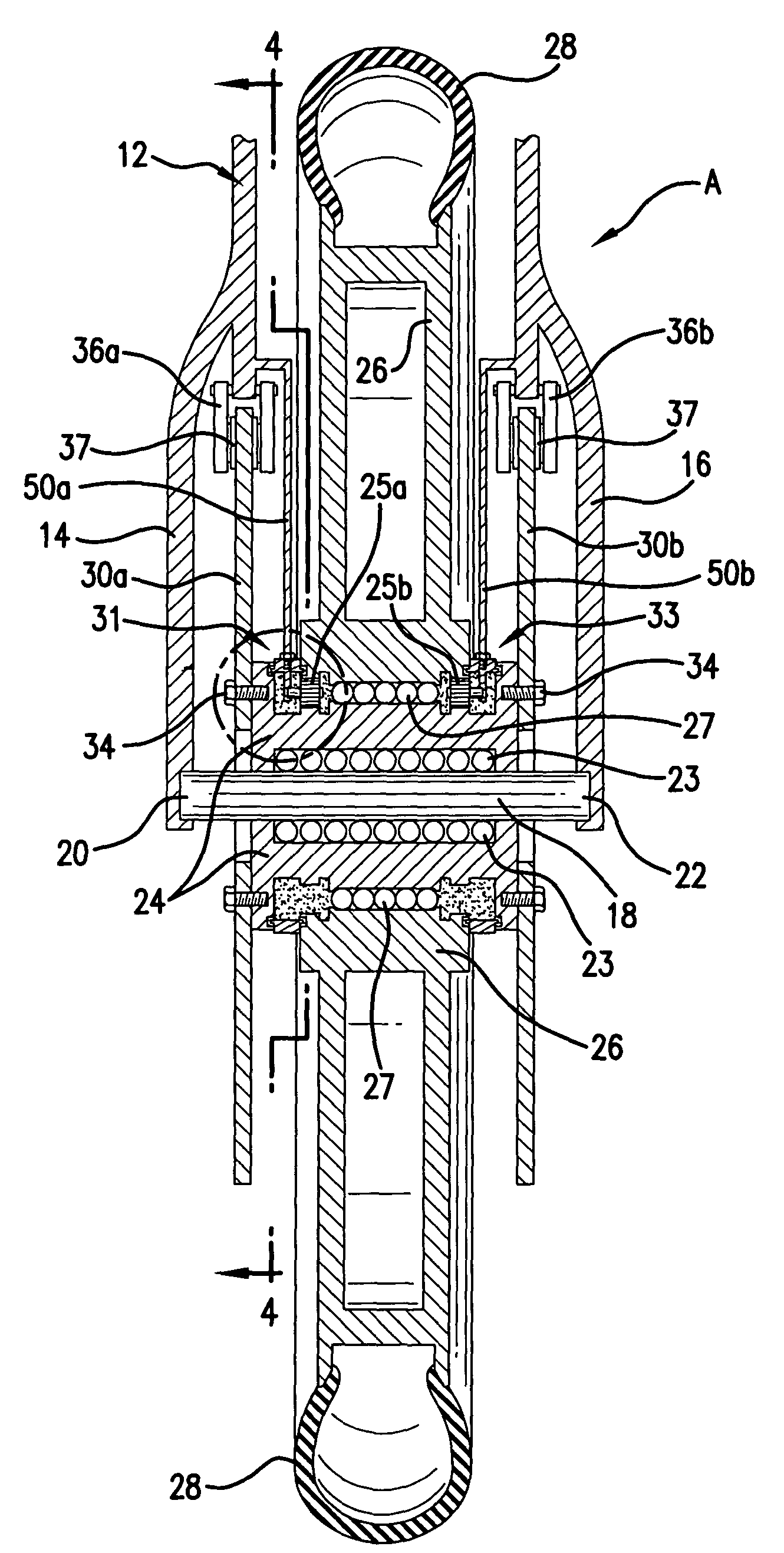
[0018]In combination with reference to the drawings, the invention will now be described in more detail. Referring first to FIG. 1, a cross-section view of a wheel assembly, designated generally as A, is shown for the front wheel of a motorcycle. As is commonly known to a person skilled in the art, a steering fork, designated generally as 12, carries the front wheel assembly on the motorcycle and allows a rider to turn the wheel and effect steering of the motorcycle.

[0019]As shown in FIG. 1, the steering fork includes a first prong 14 laterally spaced from a second prong 16, between which a wheel is carried on an axel for interacting with a road surface. The wheel assembly can generally be described to include a central wheel axel 18 having a first distal end 20 carried by first prong 14, and a second distal end 22 carried by second prong 16. A brake hub 24 is rotatably mounted to axel 18 so that the brake hub can spin about axel 18 until acted upon by braking means described herein...


PUM


Abstract

A motorcycle wheel assembly comprising a brake hub rotatably mounted to a wheel axel. A brake disc is affixed to the brake hub rotating with the brake hub. A tire hub is rotatably carried by the brake hub carrying a tire for contacting a road surface to rotate the tire hub. A transfer gear is disposed between the tire hub and the brake hub for interconnecting the brake hub and tire hub. A center gear is carried by the brake hub for engaging the transfer gear, and a ring gear is carried by the tire hub for engaging the transfer gear so that rotation of the tire hub causes the transfer gear to counter-rotate the brake hub. Accordingly, counter-rotation of the brake disc carried by the brake hub creates a counter-rotational gyroscopic force that cancels out the gyroscopic force created by rotation of the motorcycle tire and tire hub.

Description

FIELD OF THE INVENTION[0001]The present invention relates to motorcycles, and more particularly, to a wheel assembly having a counter-rotating brake disc that cancels out gyroscopic force created by rotation of the wheel.BACKGROUND OF THE INVENTION[0002]The wheels of a motorcycle, as with any rotating object, create gyroscopic force in proportion to the rate of speed at which the wheels are turning. This causes an increase in turning effort by a rider, as well as, adverse handling characteristics. In order to steer a motorcycle it must be leaned in the direction that the rider wishes to turn. When a motorcycle is leaned to one side in order to turn, the gyroscopic force of the front wheel resists the directional change. This resistance increases relative to speed. A motorcycle is a laterally unstable vehicle that steers the same at all speeds, which is to say that lateral force is equal to vertical force. Lateral force is measured by radius x rate, and vertical force is measured by ...

Claims


Application Information

Patent Timeline
Patent Type & Authority Patents(United States)
IPC IPC(8): B62L1/00F16D65/12
CPCB62L1/00F16D65/12
Inventor KASTEN, ROBERT
Owner KASTEN ROBERT
Why Eureka
Try Eureka