
Tooling plate for a flexible manufacturing system

a flexible manufacturing and tooling technology, applied in manufacturing tools, soldering devices, auxillary welding devices, etc., can solve the problems of lack of consumer demand, negative financial results for vehicle manufacturers, and inability toweld, so as to achieve the effect of convenient removal and more flexibility in a manufacturing arrangemen

Inactive Publication Date: 2005-07-19
FORD MOTOR CO
View PDF59 Cites 9 Cited by
  • Summary
  • Abstract
  • Description
  • Claims
  • Application Information

AI Technical Summary

Benefits of technology

[0015]The present invention provides an advantage in that the tooling plate can readily be removed from a workpiece presenter, therefore providing more flexibility in a manufacturing arrangement.

Problems solved by technology

Welding was not an option in many situations since the sheet metal was too thin to absorb the heat of most welding techniques.
The lack of model changeover often causes a lack of consumer demand.
Therefore, body shop capital costs generate a vicious cycle which can lead to very negative financial results for a vehicle manufacturer.
Therefore, in most instances vehicles that are dissimilar in size and function cannot be made on a common body process line.
The lack of flexibility of body process lines not only leads to increased capital cost, but is also less efficient in the utilization of maintenance equipment and purchasing.
Maintenance and the associated training cost of operational personnel is also increased.
This has generally not saved money and time.

Method used


Image

  • Tooling plate for a flexible manufacturing system
  • Tooling plate for a flexible manufacturing system
  • Tooling plate for a flexible manufacturing system

Examples


Embodiment Construction

[0034]The flexible manufacturing system of the present invention is demonstrated in the environment of a weld process line for assembling a body of an automotive vehicle. Metal components of the body assembly for an automotive vehicle are first acted upon in a metal stamping facility. In some instances, the stamping facility will be located next to a vehicle assembly plant. However, most automotive manufacturers have fewer stamping facilities than assembly facilities. Therefore, often the stamped metal workpieces are shipped by rail or truck to an assembly plant.

[0035]Upon arrival at the assembly plant, the stamped workpieces are delivered to the body shop of the assembly facility. In the body shop, the body shell of the vehicle is assembly primarily on a weld processing line as will be further explained. After the body shell of the vehicle has been assembled in the weld processing line, the body is delivered to the paint shop of the assembly plant, wherein the body is painted. Ofte...


PUM


Abstract

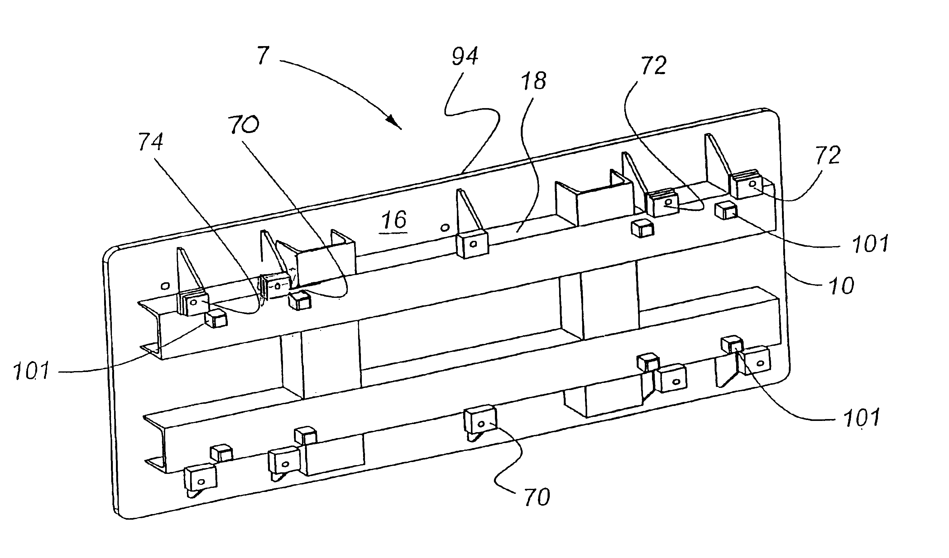
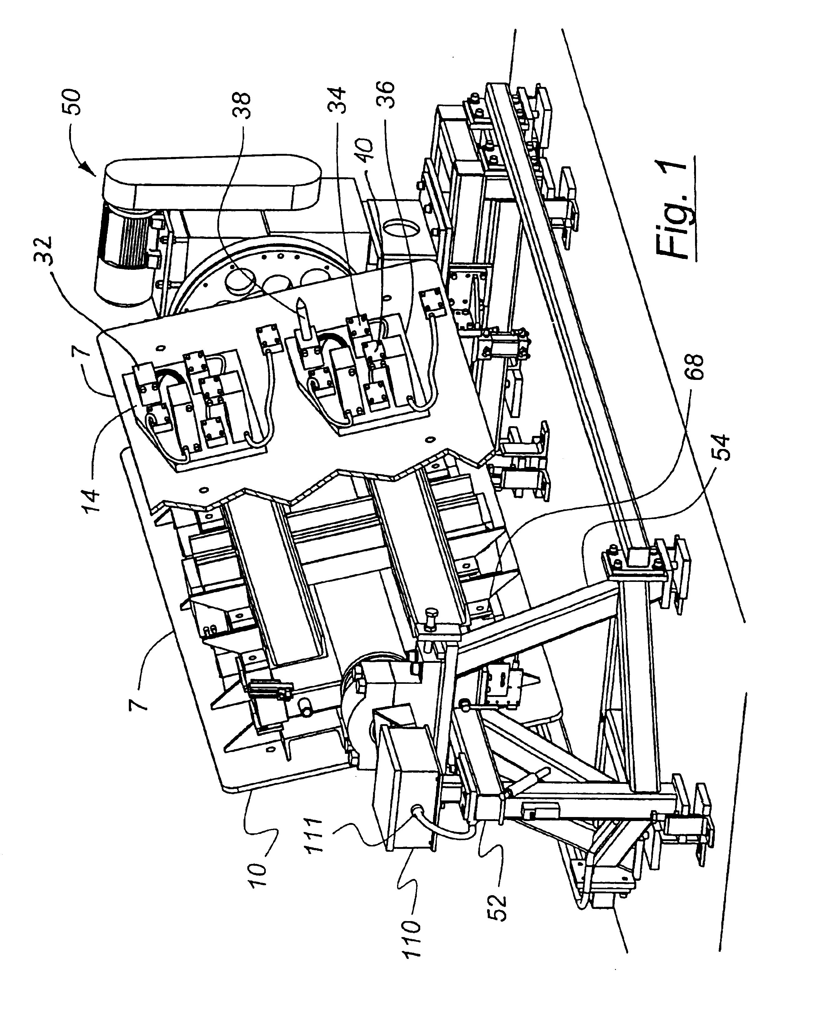
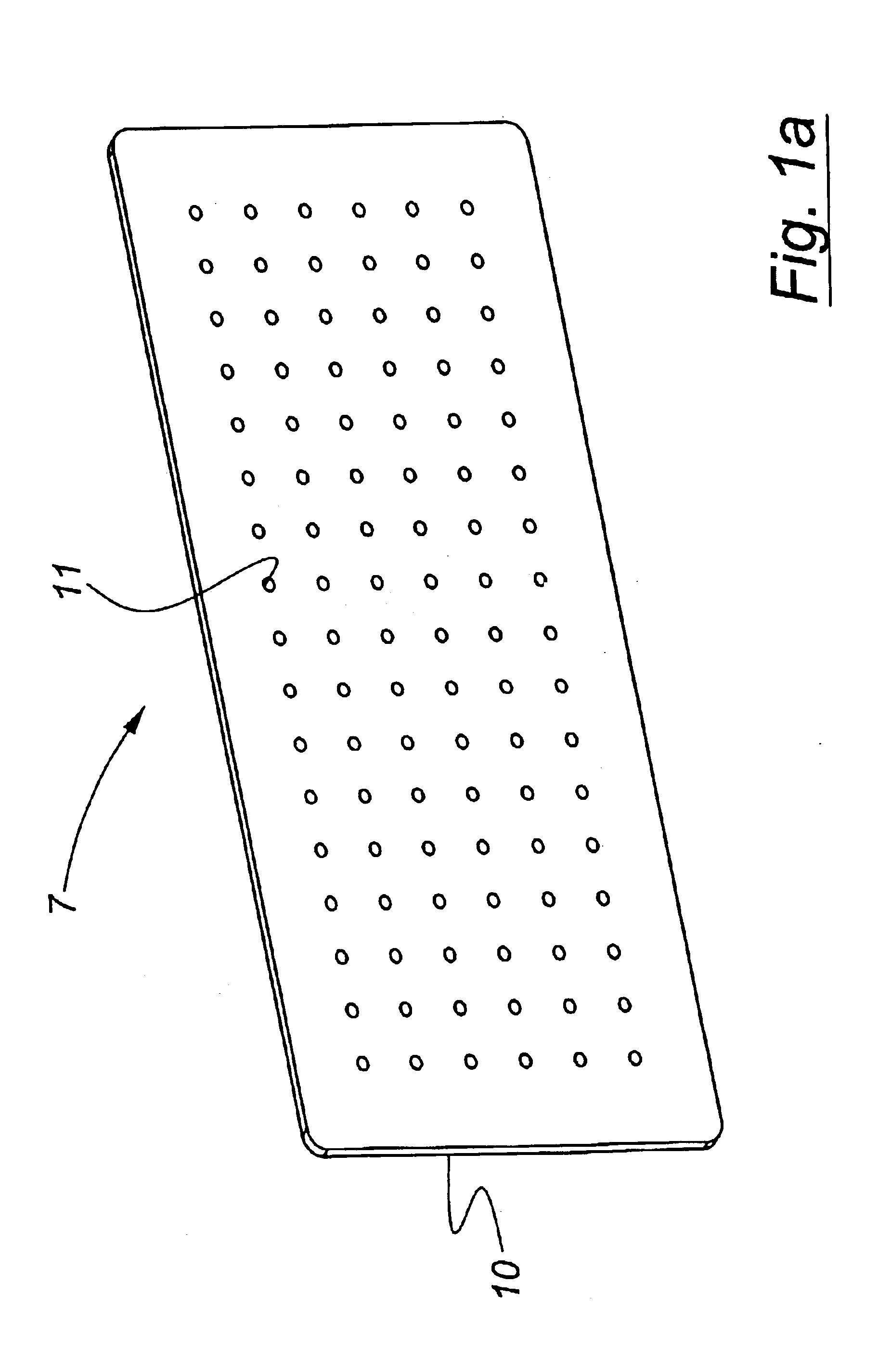
A tooling plate to fixture a workpiece for a vehicle subassembly is provided, including a planar body 10 for supporting fixture tools 32, 34 for holding a workpiece, a connector mechanism to allow the planar body 10 to be removably connected with a workpiece presenter 50, and a locater mechanism 70, 72, 74 to locate the planar body 10 with respect to the workpiece presenter 50 in a repeatable manner.

Description

FIELD OF THE INVENTION[0001]The field of the present invention is that of tooling plates utilized in manufacturing. The tooling plate of the present invention is particularly useful in automotive manufacturing.BACKGROUND OF THE INVENTION[0002]In the genesis of automotive manufacturing, vehicle bodies were carriages fabricated from wood and leather. Hence the term “horseless carriage” came to describe automobiles. Subsequently, vehicles were developed having a steel frame chassis which was connected with the drive train of the vehicle. A steel vehicle body was then mated with the chassis.[0003]Initially, steel vehicle bodies were connected together primarily by rivets and threaded fasteners. Welding was not an option in many situations since the sheet metal was too thin to absorb the heat of most welding techniques. In the mid-20th century a welding technique was developed which could weld together relatively thin overlapping members of sheet metal, commonly referred to as spot weldi...

Claims


Application Information

Patent Timeline
Patent Type & Authority Patents(United States)
IPC IPC(8): B23Q16/00B23K37/04B23P21/00B62D65/00B62D65/18
CPCB23K37/0426B23P21/004B23Q16/001B62D65/18B23P2700/50
Inventor GHUMAN, ABIDROBERTSON, JOHN E.GIEZENTANNER, BRUCE
Owner FORD MOTOR CO
Learn More