Longitudinal plunging unit with a hollow profiled journal

a technology of longitudinal plunging unit and hollow profile, which is applied in the direction of yielding coupling, shaft, road vehicle, etc., can solve the problems of inability to save so far, and achieve the effect of high strength

Inactive Publication Date: 2005-07-19
GKN LOBRO
View PDF12 Cites 45 Cited by
  • Summary
  • Abstract
  • Description
  • Claims
  • Application Information

AI Technical Summary

Benefits of technology

[0006]It is therefore an object of the present invention to provide a longitudinal plunging unit of the foregoing type which combines a high degree of strength with a lightweight design.

Problems solved by technology

This measure permits the greatest savings in respect of weight and material at the profiled journal, which savings have so far not been possible.

Method used


Image

  • Longitudinal plunging unit with a hollow profiled journal
  • Longitudinal plunging unit with a hollow profiled journal
  • Longitudinal plunging unit with a hollow profiled journal

Examples


Embodiment Construction

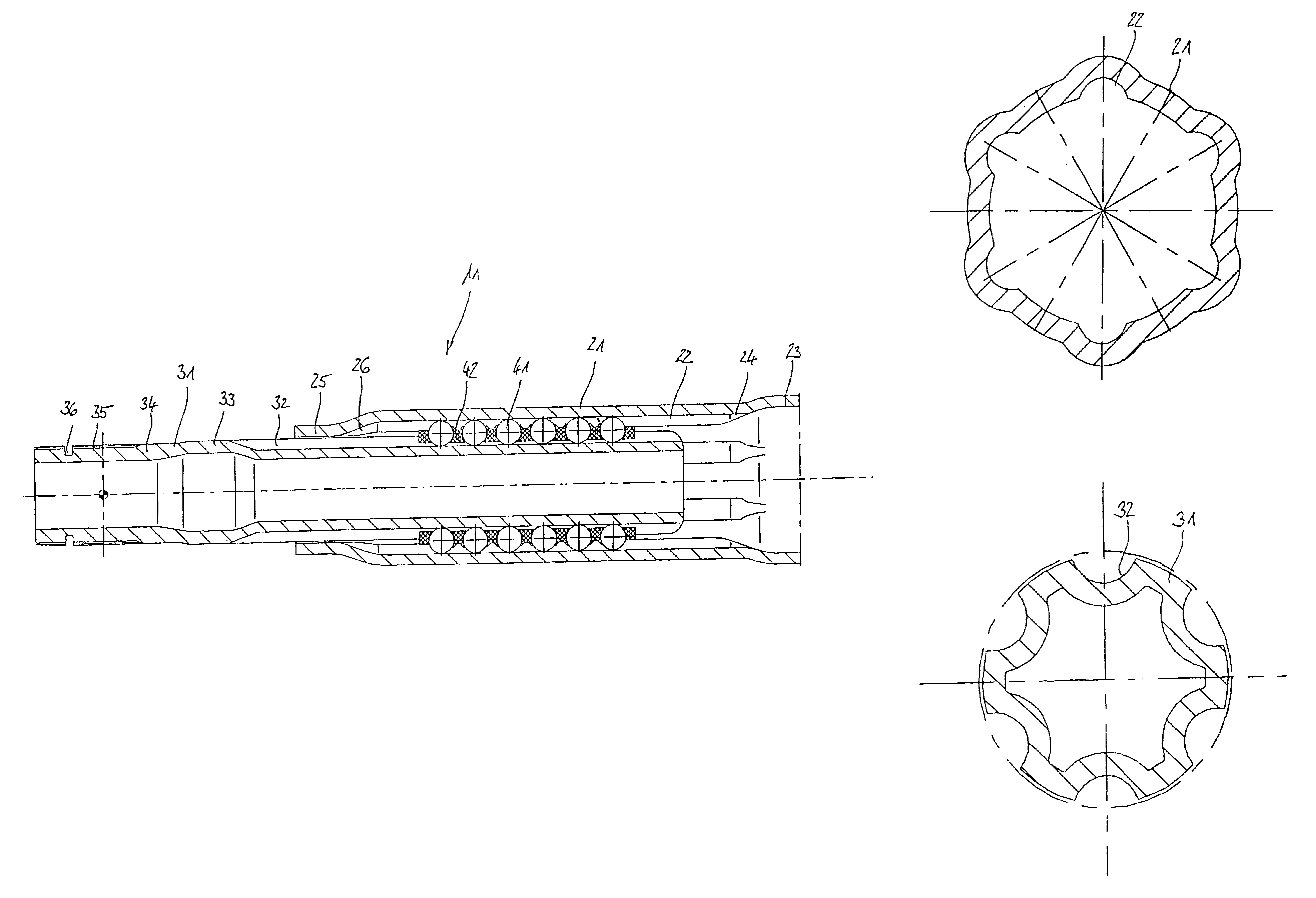
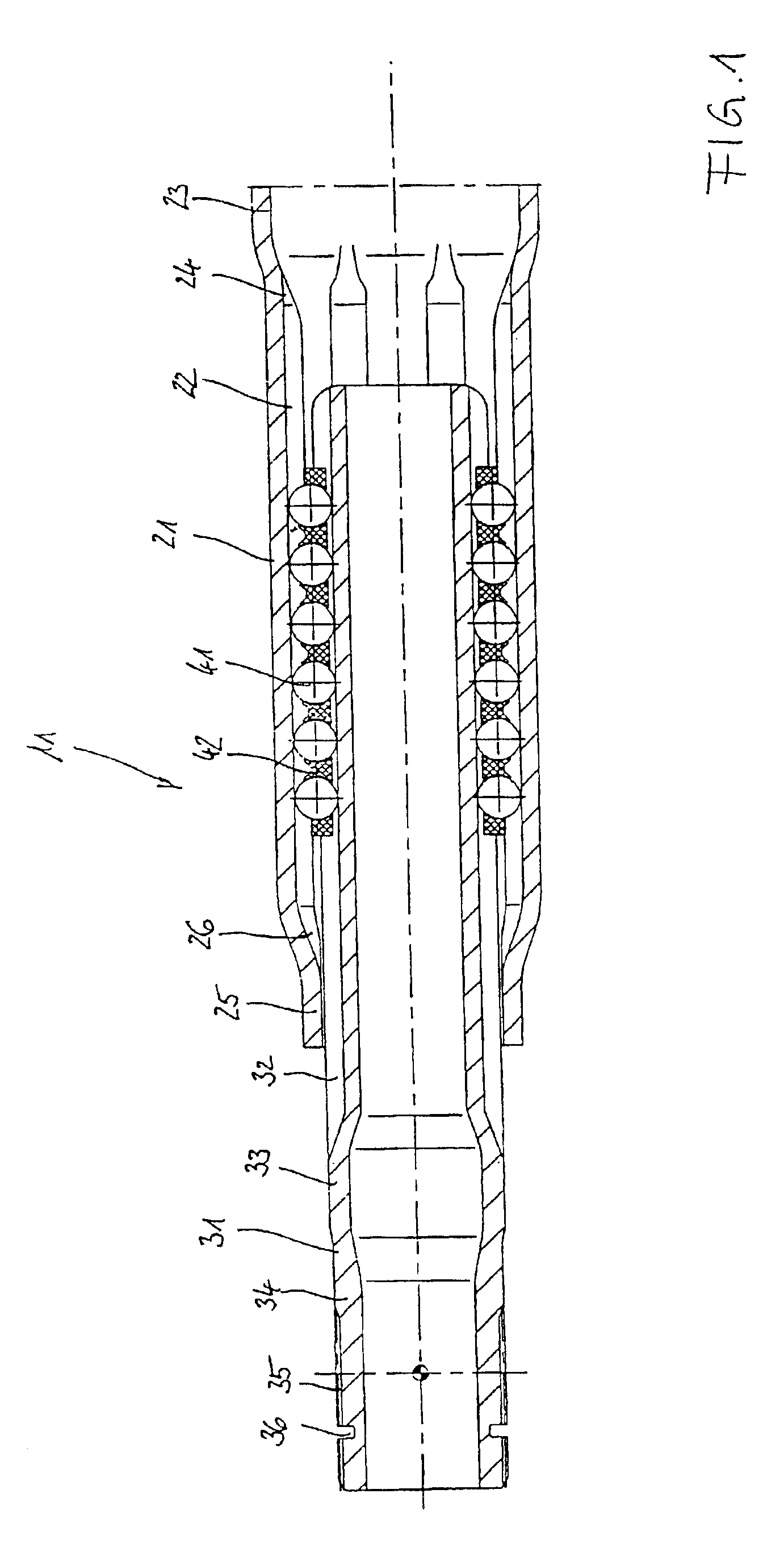
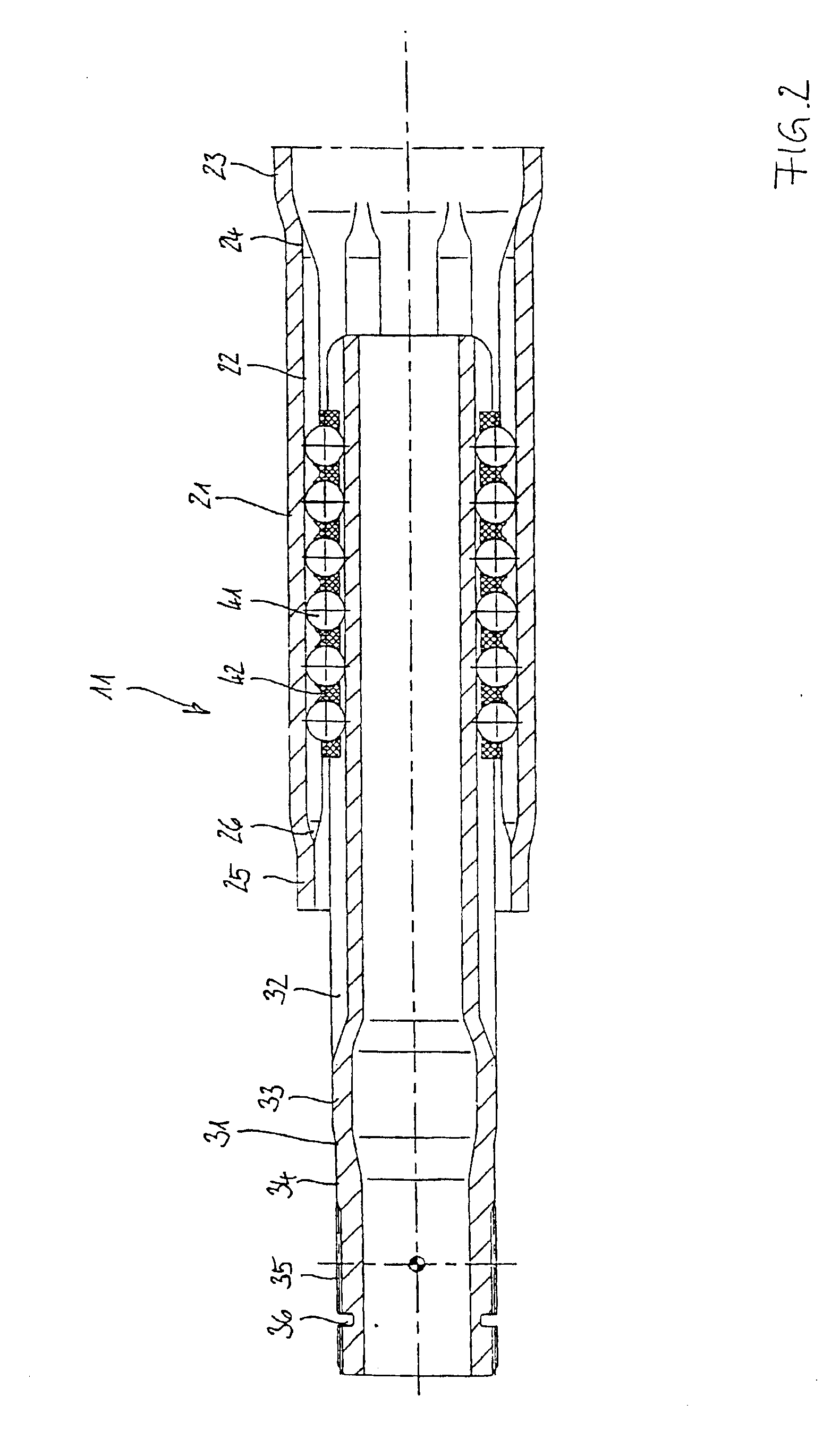
[0025]FIGS. 1 and 2 will be described jointly below. They each show a longitudinal section through an inventive axial plunging unit 11 which comprises a profiled sleeve 21, a profiled journal 31, groups of torque transmitting balls 41 and a sleeve-shaped ball cage 42. On the right, the profiled sleeve 21 can be connected to a first attachment part, such as a tubular shaft. On the left, the profiled journal 31 can be connected to a second attachment part, such as a slid-on joint component. The profiled sleeve 21 comprises a material with a substantially uniform wall thickness and, on its inside, comprises longitudinally extending ball grooves 22. At the end of the first attachment part, the profiled sleeve 21 is expanded towards a first cylindrical projection 23 whose inner diameter is greater than an enveloping circle around the ball 41 in its design-related functionally accurate position as held by the cage 42. The ball cage can thus be inserted from the right through the first cyl...


PUM


Abstract

A longitudinal plunging unit (11) for torque transmitting purposes in a shaft assembly, comprising an outer profiled sleeve (21) having circumferentially distributed, inner, longitudinally extending first ball grooves (22) to be connected to a first attachment part, a profiled journal (31) positioned inside the outer profiled sleeve (21) and having circumferentially distributed, outer, longitudinally extending second ball grooves (32) to be connected to a second attachment part, groups of balls (41) arranged in pairs of first and second ball grooves (22, 32), and a sleeve-shaped ball cage (42) which is positioned in the annular space between the profiled sleeve (21) and the profiled journal (31) and which fixes the groups of balls (41) in their respective positions relative to one another. The profiled journal (31) is a hollow journal comprising a material with a substantially uniform wall thickness with a maximum deviation of ±15%.

Description

TECHNICAL FIELD[0001]The invention relates to a longitudinal plunging unit for torque transmitting purposes in a shaft assembly. The unit includes an outer profiled sleeve having circumferentially distributed, inner, longitudinally extending first ball grooves to be connected to a first attachment part, a profiled journal positioned inside the outer profiled sleeve and having circumferentially distributed, outer, longitudinally extending second ball grooves to be connected to a second attachment part, groups of balls arranged in pairs of first and second ball grooves, and a sleeve-shaped ball cage which is positioned in the annular space between the profiled sleeve and the profiled journal and which fixes the groups of balls in their respective positions relative to one another.BACKGROUND OF THE INVENTION[0002]Such axial plunging units serve the transmission of torque in shaft assemblies which, when in operation, are subject to changes in length. These changes in length in a motor v...

Claims


Application Information

Patent Timeline
Patent Type & Authority Patents(United States)
IPC IPC(8): F16C3/02F16C3/03F16D3/02F16D3/06
CPCF16C3/035F16D3/065F16C2326/24
Inventor SCHWARZLER, PETERCERMAK, HERBERTBERGER, ARNE
Owner GKN LOBRO
Why Eureka
Try Eureka