Apparatus and process for producing electrophoretic device

a technology of electrophoretic devices and apparatus, applied in the direction of fluid pressure measurement, liquid/fluent solid measurement, peptide measurement, etc., can solve the problems of flickering and low luminance of light sources, visual load on human eyes, and difficulty in recognizing characters

Inactive Publication Date: 2005-07-19
CANON KK
View PDF9 Cites 58 Cited by
  • Summary
  • Abstract
  • Description
  • Claims
  • Application Information

AI Technical Summary

Benefits of technology

[0033]A more specific object of the present invention is to provide an apparatus and a process for producing a high-quality electrophoretic (display) device wherein charged phoretic particles in a dispersion liquid are easily and evenly distributed to respective cells or pixels even in the case of a very small gap between two substrates or the case of using a flexible substrate.

Problems solved by technology

However, such liquid crystal display devices are still accompanied with problems of visual load on human eyes, such as difficulty of recognizing characters on display depending on a viewing angle or due to reflection light, and flickering and low luminance of light sources.
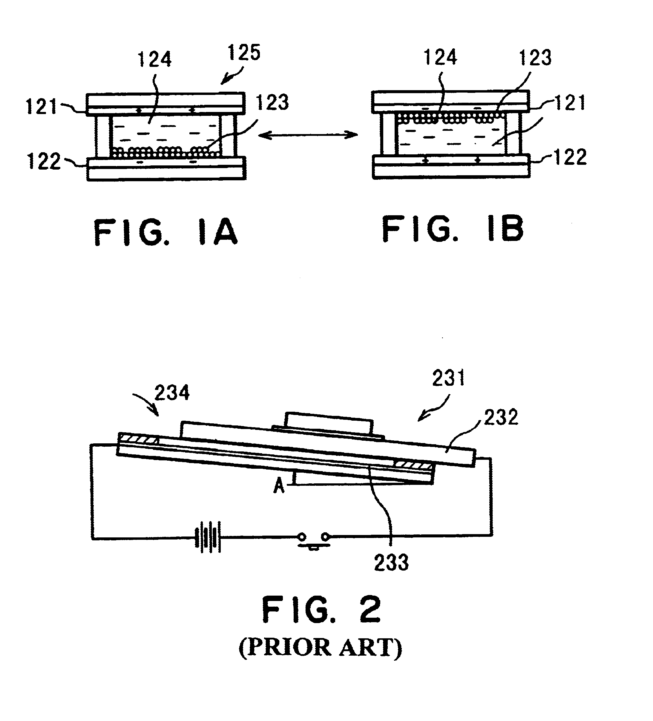
The method of JP-A 11-38898 may be satisfactory in the case of a large gap between the substrates, but at a smaller gap, the flow of charged phoretic particles is retarded compared with that of the dispersion liquid medium, so that the density of charged phoretic particles is liable to be higher at the injection port, and a uniform dispersion becomes difficult.
Further, in this method, it is necessary to provide the apparatus with an electrode 233 having an area identical to that of the substrate 232, thus leaving problems regarding mass productivity and production cost.
The diffusion of attached electrophoretic particles relying on only the electrophoretic effect is accompanied with several problems.
The diffusion by the electrophoretic effect alone may require application of a large-voltage between the electrodes, which is liable to cause an electric insulation breakdown of the electrophoretic apparatus.

Method used


Image

  • Apparatus and process for producing electrophoretic device
  • Apparatus and process for producing electrophoretic device
  • Apparatus and process for producing electrophoretic device

Examples


first embodiment

(First Embodiment)

[0061]FIG. 6 is a schematic illustration (partly in section) of an embodiment of the apparatus for producing an electrophoretic display device according to the present invention. Referring to FIG. 6, an apparatus 1011 includes a first vessel 1014 as a storage means for holding a dispersion liquid 1013 containing charged phoretic particles 1012 dispersed therein; a second vessel for holding a dispersion liquid medium 1015 not containing such charged phoretic particles 1012; stirring means 1017 for stirring the dispersion liquid (medium) 1013 and 1015; a substrate-holding means 1019 for holding a substrate 1018; and a voltage application means 10110 for applying a voltage to an electrode formed on the substrate 1018.

[0062]It is further preferred for the substrate-holding means 1019 to have functions of conveying and vibrating the substrate 1018. The apparatus 1011 further includes a first concentration detection means 10111 for detecting the concentration of charged ...

example 1-1

[0075]An electrophoretic display device was prepared by using an apparatus according to the present invention as shown in FIG. 1.

[0076]A dispersion liquid 1013 was prepared by dispersing ca. 1-2 μm-dia. black charged phoretic particles and a charge control agent in a dispersion liquid medium comprising principally aliphatic hydrocarbons (“ISOPER” (trade name), made by Exxon Co.) and placed in a first vessel 1014. As positive charge control agents, it is possible to use a naphthenic acid salt of a metal, such as cobalt, manganese or iron, zirconium octenate, etc. and as negative control agents, it is possible to use lecithin, calcium petroleum-sulfonate, calcium alkylbenzene-sulfonate, sodium dioctylsulfonate, alkylalanine, etc. Such a charge control agent can also be incorporated in (charged) phoretic particles.

[0077]Then, a dispersion liquid medium 1015 (identical to the above) not containing charged phoretic particles was placed in a second vessel 1016. The liquids within the firs...

second embodiment

(Second Embodiment)

[0082]FIG. 7 is a schematic illustration (partly in section) of an embodiment of the apparatus for producing an electrophoretic display device of the present invention. Referring to FIG. 7, an apparatus 2011 includes a substrate-holding means 2013 for holding a substrate 2012 with electrodes formed thereon, a voltage application means 2014 for applying a voltage to the electrodes formed on the substrate 2012, a nozzle 2017 as a means for ejecting a dispersion liquid 2016 containing charged phoretic particles 2015 dispersed therein, and a pump 2018 for supplying the dispersion liquid 2016 to the nozzle 2017. The apparatus 2011 further includes a first vessel 2019 for storing the dispersion liquid 2016 to be ejected and receiving an excess of the ejected dispersion liquid 2016, an optical density detection means 20110 for detecting the density of the charged phoretic particles 2015 deposited on the electrodes, a density detection means 20111 for measuring the concen...


PUM

PropertyMeasurementUnit
voltageaaaaaaaaaa
frequencyaaaaaaaaaa
voltagesaaaaaaaaaa

Abstract

A system (apparatus and process) for producing an electrophoretic (display) device is provided for allowing production of such a device wherein electrophoretic particles in the dispersion liquid are easily and evenly distributed to respective cells (pixels) between two substrates of the device even in the case of a very small gap between the two substrates or the case of using a flexible substrate. The system includes a storage unit for a dispersion liquid containing the charged phoretic particles dispersed therein, a stirrer for stirring the dispersion liquid, a substrate-holder for holding the substrate in the dispersion liquid, and a voltage source for applying a voltage to the electrodes formed on the substrate thereby depositing the electrophoretic particles on the electrodes.

Description

FIELD OF THE INVENTION AND RELATED ART[0001]The present invention relates to an apparatus for producing an electrophoretic (display) device wherein electrophoretic particles are moved between electrodes to effect a display, and also a process for producing such an electrophoretic (display) device including a step of filling an electrophoretic device with an electrophoretic dispersion liquid containing charged (electro-)phoretic particles. More specifically, the present invention relates to a process for producing an electrophoretic device including a step of filling with charged phoretic particles a very small gap or spacing between a pair of substrates, of which at least one is provided with an electrode, of the electrophoretic device.[0002]In recent years, accompanying the progress of data processing apparatus, there has been an increasing demand for a display device requiring a small power consumption and a small thickness, and extensive study and development have been made on de...

Claims


Application Information

Patent Timeline
Patent Type & Authority Patents(United States)
IPC IPC(8): G02F1/01G02F1/167G02F1/1679
CPCG02F1/167G02F1/1679
Inventor IKEDA, TSUTOMUUKIGAYA, NOBUTAKA
Owner CANON KK
Why Eureka
Try Eureka