Carbon nanotube suspension

a carbon nanotube and suspension technology, applied in the manufacture of electric discharge tubes/lamps, non-metal conductors, conductors, etc., can solve the problems of difficult distribution of high-viscosity carbon nanotube mixtures, difficult to obtain an even surface, and difficult to achieve uniform electric fields to generate electron beams. , to achieve the effect of easy formation

Inactive Publication Date: 2006-01-12
TECO NANOTECH CO LTD
View PDF3 Cites 10 Cited by
  • Summary
  • Abstract
  • Description
  • Claims
  • Application Information

AI Technical Summary

Benefits of technology

[0005] A carbon nanotube suspension is provide to serve as the source material for the electron emission source of a field-emission display. The electron-emission source can be easily formed by a coating process.

Problems solved by technology

With such high viscosity, it is very difficult to obtain an even surface.
As a result, the distance between the electron-emission layer and the gate layer of the same cathode unit is non-uniform, such that the electric field cannot be uniform to generate uniform electron beams in each position.
The very high viscosity of the carbon nanotube mixture is very difficult to distribute.
Even when the carbon nanotube mixture is distributed by mechanical and physical property, an even thickness is still difficult to obtain.
Therefore, non-uniform electron beams are emitted.
As a result, uneven brightness in a single luminescent unit occurs, such that the image quality is degraded.
In addition, although the carbon nanotube mixture has very high viscosity, the adhesion is insufficient.
Therefore, adhesion additive such as glass powder is often required to further complicate the process.

Method used


Image

  • Carbon nanotube suspension
  • Carbon nanotube suspension
  • Carbon nanotube suspension

Examples


Embodiment Construction

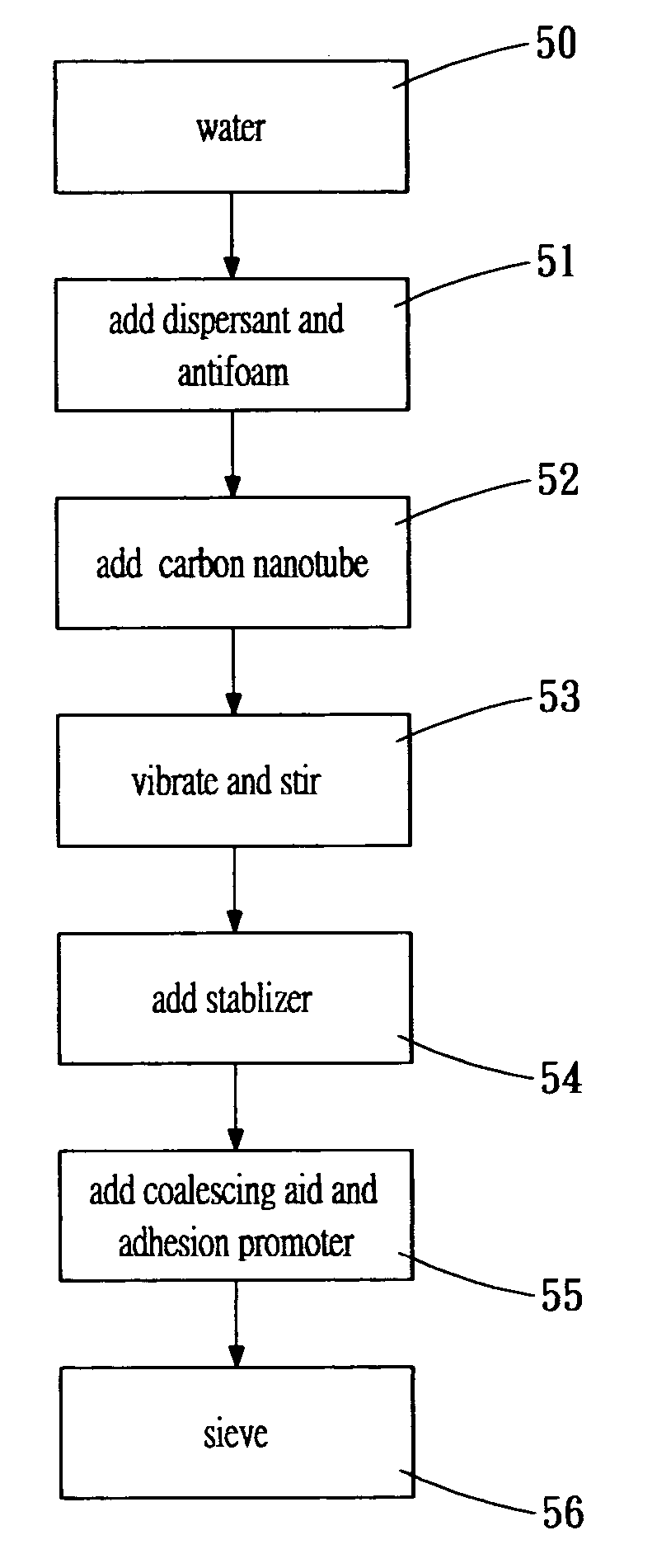
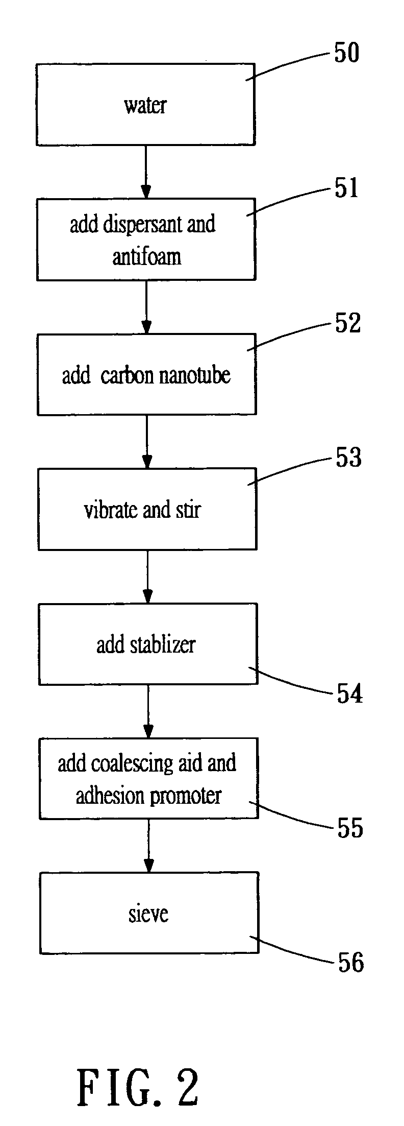
[0013] A carbon nanotube suspension is provided using water as the solvent, which is added with dispersant, stabilizer, coalescing aid, adhesion promoter and antifoam to form a low-viscosity solution. A carbon nanotube no longer than 1 micron is then immersed in the low-viscosity solution to form the carbon nanotube suspension. The proportion of the solutes and the nanotube is as follows: [0014] 1. carbon nanotube: 5% to 20%; [0015] 2. coalescing aid: 5% to 20%, including aluminum sodium sulfate, silane coupling agent, alkyd resin or tetra-ethyl-ortho-silicate (TEOS), or the combination of any of these components, such that the suspension can be easily attached to the glass substrate of the field-emission display; [0016] 3. adhesion promoter: 1% to 5%, including PVA, PVP, methyl cellulose, ethyl cellulose, sodium polyacrylate, or ammonium polyacrylate for increasing adhesion of the suspension, so as to control the film thickness. [0017] 4. stablizer: 0.5% to 5%, including one of amm...


PUM

PropertyMeasurementUnit
adhesionaaaaaaaaaa
of timeaaaaaaaaaa
brightnessaaaaaaaaaa

Abstract

A carbon nanotube suspension uses water as the basic solvent added with dispersant, stabilizer, coalescing aid, adhesion promoter, and a carbon nanotube. The basic solvent and the above solutes form a low viscosity solvent with carbon nanotube suspending therein. Therefore, the carbon nanotube suspension is formed to serve as a source material of the electron emission source of a field-emission display. That is, the carbon nanotube can be coated on a surface for forming the carbon nanotube electron-emission layer.

Description

BACKGROUND OF THE INVENTION [0001] The present invention relates in general to a carbon nanotube suspension, and more particularly, to a solvent containing carbon nanotube suspending therein. The carbon nanotube suspension can be used for forming an electron-emission source of a field-emission display. [0002] The field-emission display is a very newly developed technology. Being self-illuminant, such type of display does not require a back light source like the liquid crystal display (LCD). In addition to the better brightness, the viewing angle is broader, power consumption is lower, response speed is faster (no residual image), and the operation temperature range is larger. The image quality of the field-emission display is similar to that of the conventional cathode ray tube (CRT) display, while the dimension of the field-emission display is much thinner and lighter compared to the cathode ray tube display. Therefore, it is foreseeable that the field-emission display may replace ...

Claims


Application Information

Patent Timeline
Patent Type & Authority Applications(United States)
IPC IPC(8): H01B1/00
CPCB82Y10/00H01B1/24H01J2201/30469H01J31/123H01J9/025Y10S977/742Y10S977/832Y10S977/835
Inventor HSIAO, CHUN-YENLI, YU-ANTSAI, JIN-LUNGCHENG, KUEI-WEN
Owner TECO NANOTECH CO LTD
Why Eureka
Try Eureka