Rotor assembly for an electric motor and electric motor with internal rotor

Inactive Publication Date: 2005-07-19
MINEBEAMITSUMI INC
View PDF18 Cites 18 Cited by
  • Summary
  • Abstract
  • Description
  • Claims
  • Application Information

AI Technical Summary

Benefits of technology

[0012]It is the object of the invention to provide a rotor assembly for an electric motor as well as an internal-rotor electric motor which can be assembled with minor-engineering within a short time and which ensure that no foreign particles penetrate into the interior of the motor, and in particular into the working air gap, during assembly and operation.

Problems solved by technology

A problem arising in the manufacture of such an internal-rotor electric motor is that when the rotor assembly is inserted into the interior space of the stator, ferro-magnetic particles may be abraded from the rotor magnet and may enter the working air gap which is essentially defined by the outer contour of the rotor magnet and the inner contour of the stator.
Moreover, internal-rotor electric motors according to the prior art have the disadvantage of a relative time-consuming assembly, because it is mainly a sequential assembly in which the stator and at least one bearing must be successively pre-assembled in the housing and then the rotor assembly must be fitted into the stator and bearing.
This assembling step is made much more difficult by the magnetic forces which come from the rotor magnet and are radially and axially directed by interaction with the stator iron core so that a contactless concentric fitting of the rotor is not possible at all or is possible only with major engineering.
The arrangement of DE 32 37 196 has the disadvantage that motors having ironless field windings always run with a very low efficiency because of the large air gap.
However, for the delivery of larger torques, as is required for motor vehicle applications, for example, they are completely unsuited.
Moreover, the internal-rotor motor of DE 32 37 196 has the disadvantage that the hermetic encapsulation of the rotor assembly does not allow a direct, mechanical coupling of a load, but that the torque transmission from the rotor to a shaft must be only in an indirect manner, e.g. by means of magnetic coupling, as is described in the patent specification.

Method used


Image

  • Rotor assembly for an electric motor and electric motor with internal rotor
  • Rotor assembly for an electric motor and electric motor with internal rotor
  • Rotor assembly for an electric motor and electric motor with internal rotor

Examples


Embodiment Construction

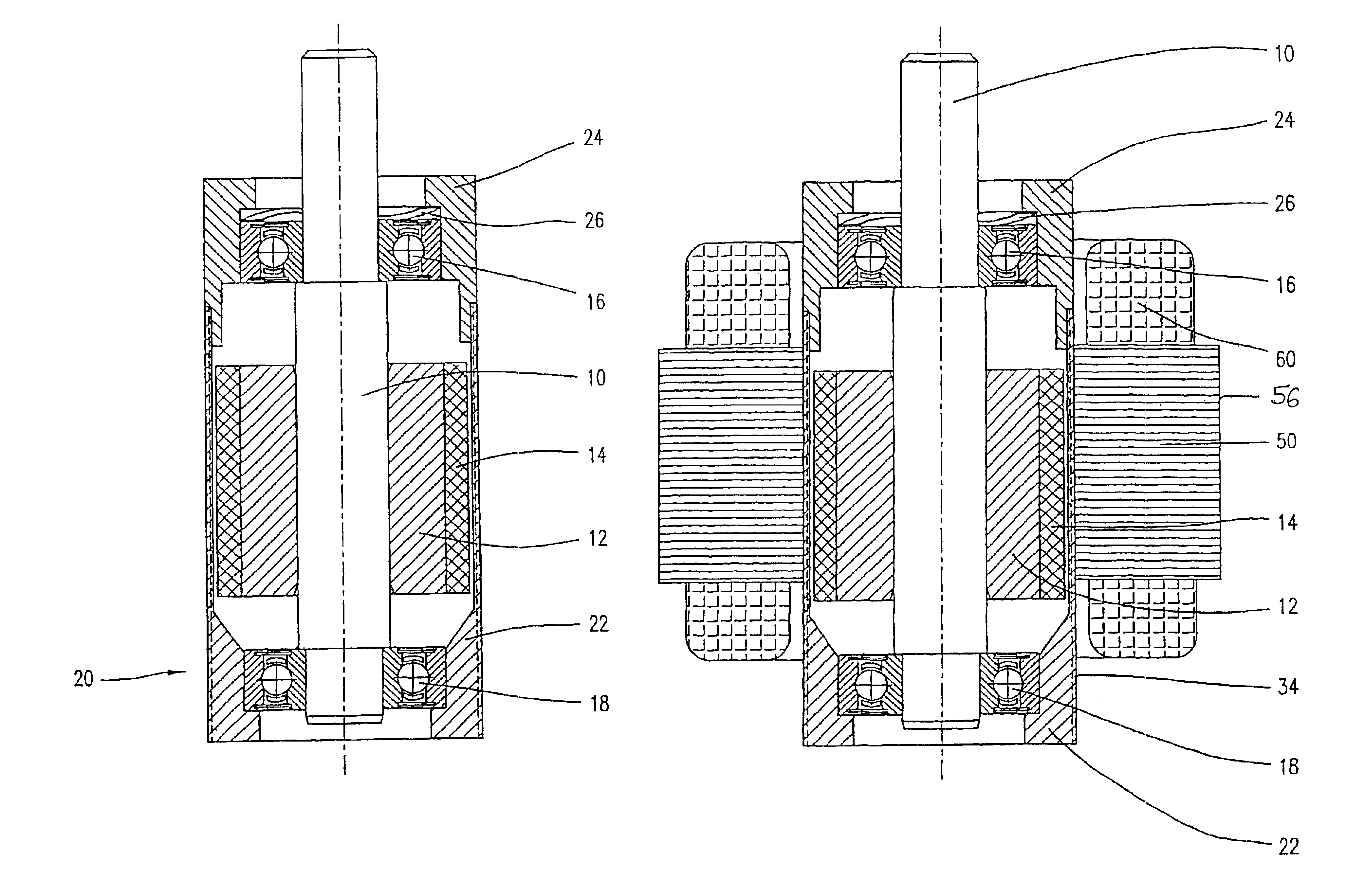
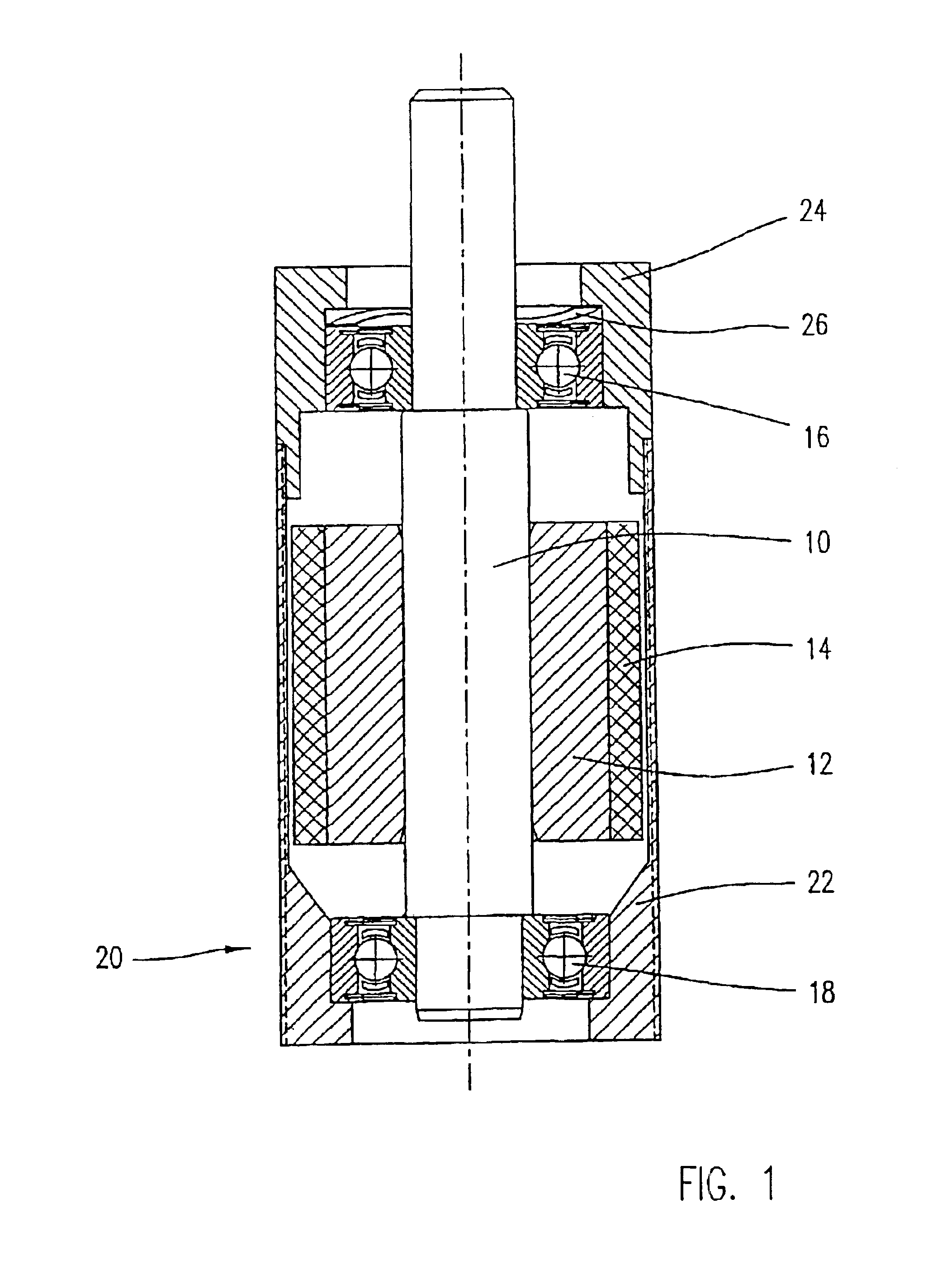
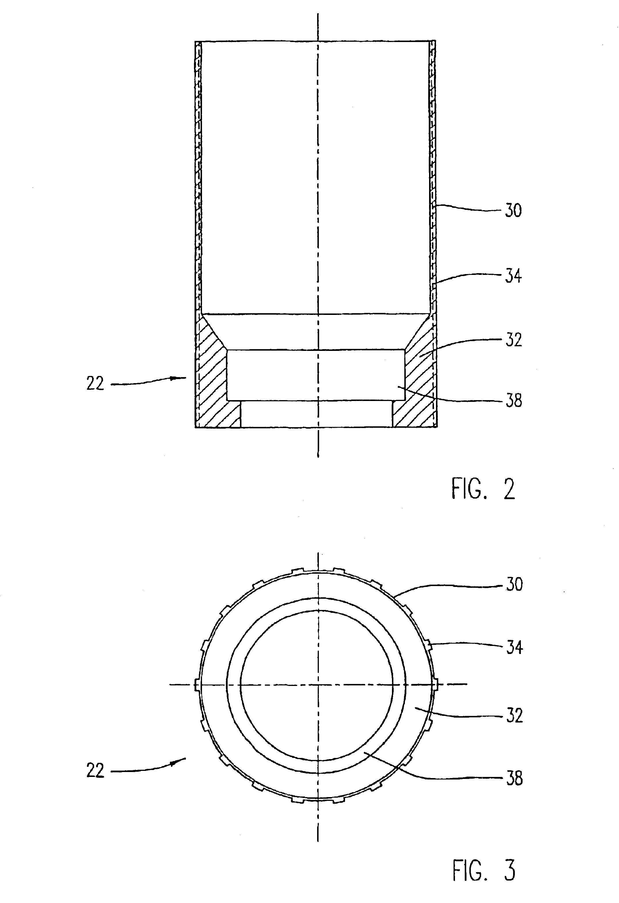
[0037]FIG. 1 shows a cross-sectional view of a preferred embodiment of a rotor assembly according to the invention. The rotor assembly according to the invention comprises a rotor shaft 10 carrying a yoke ring 12 made of a soft magnetic material such as iron. A preferably annular permanent magnet 14 is attached on the yoke ring 12. The shaft 10 is rotatably journaled in bearings 16, 18, wherein the bearings 16, 18 may be formed as antifriction or friction bearings and specifically as roller bearings. The rotor which is formed here by the rotor shaft 10, the yoke ring 12 and the permanent magnet 14 is enclosed in a sleeve 20 comprising an encapsulation section 22 and a flange section 24 which will be explained in detail with reference to the FIGS. 2 to 5.

[0038]The bearings 16, 18 may be pre-mounted on the rotor shaft 10 and are placed in the end faces of the sleeve sections 22, 24 and are pressed in them and / or adhered to them or are held in another suitable way. In the illustrated e...


PUM


Abstract

An electric motor having a stator arranged on a sleeve; and a rotor assembly having a rotor shaft and at least one permanent magnet arranged on the rotor shaft, the rotor shaft being rotatbly housed in the sleeve. An external dimension of the rotor assembly and an internal dimension of the stator are selected such that the rotor assembly is free to move in the axial direction while the rotor assembly is inserted into the stator. The rotor assembly is aligned within the stator in the magnetic center of the stator by self-centering magnetic forces.

Description

CROSS REFERENCE TO RELATED APPLICATIONS[0001]This application is a national stage U.S. Patent Application and claims all rights of priority to International PCT Application No. PCT / EP01 / 07796, filed Jul. 4, 2001 (pending), which in turn claimed all rights of priority to German Patent Application No. 100 34 302.3, filed Jul. 14, 2000 (pending).FIELD OF INVENTION[0002]The present invention refers to a rotor assembly for an electric motor which has a rotor shaft and at least one permanent magnet arranged on the rotor shaft, an internal-rotor electric motor employing such a rotor assembly, and a method for manufacturing such an internal-rotor electric motor.[0003]The invention relates to the field of brushless electric motors having permanent magnets and specifically to the field of d.c. motors configured as so-called internal-rotor electric motors. Internal-rotor electric motors comprise a rotor assembly which includes a rotor shaft and one or more permanent magnets arranged on the rot...

Claims


Application Information

Patent Timeline
IPC IPC(8): H02K5/12H02K5/128H02K15/02H02K5/15H02K15/03H02K21/14
CPCH02K5/128H02K1/27
Inventor RAPP, HARALD
Owner MINEBEAMITSUMI INC
Why Eureka
Try Eureka