Internal rotor motor

a rotor motor and internal technology, applied in the direction of dynamo-electric components synchronous machines with rotating armatures and stationary magnets, etc., can solve the problem of general insufficient power of ironless stators, and achieve the effect of improving characteristics, reducing cogging torque, and reducing cogging torqu

Inactive Publication Date: 2005-07-19
EBM PAPST ST GEORGEN & -
View PDF33 Cites 67 Cited by
  • Summary
  • Abstract
  • Description
  • Claims
  • Application Information

AI Technical Summary

Benefits of technology

[0005]It is therefore an object of the invention to provide a sufficiently powerful internal rotor motor with minimized cogging torque. According to the invention, this object is achieved by shaping the magnetic circuit of the rotor in such a way that respective reluctance torques gener

Problems solved by technology

In the context of many drive applications, this reluctance torque is disruptive, so that there one is forced to use so-called “ironless” stator windings,

Method used


Image

  • Internal rotor motor
  • Internal rotor motor
  • Internal rotor motor

Examples


Embodiment Construction

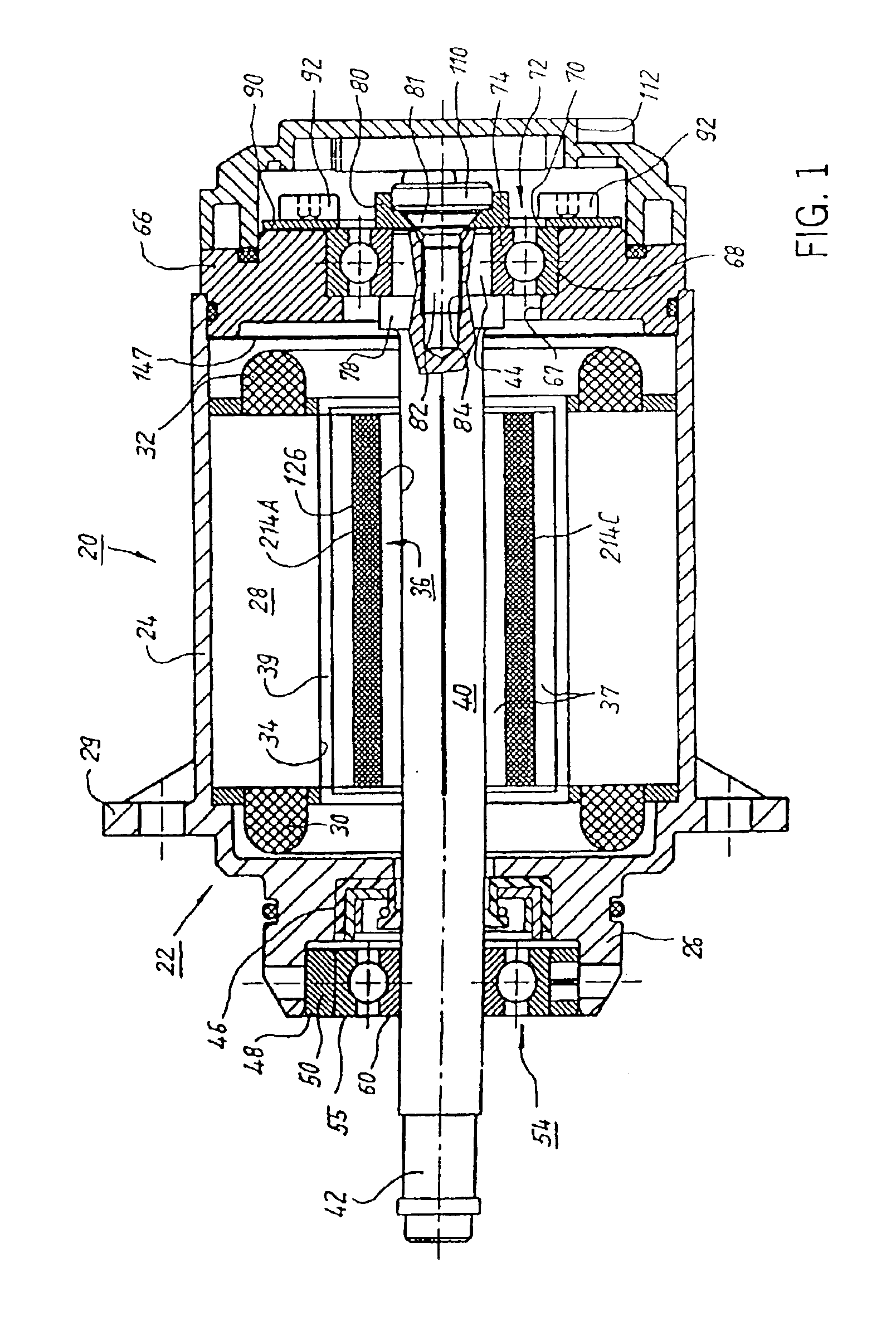
[0025]FIG. 1 shows an electronically commutated internal rotor motor 20 with a housing 22 having a cylindrical housing portion 24, an A-side bell 26 and a securing flange 29.

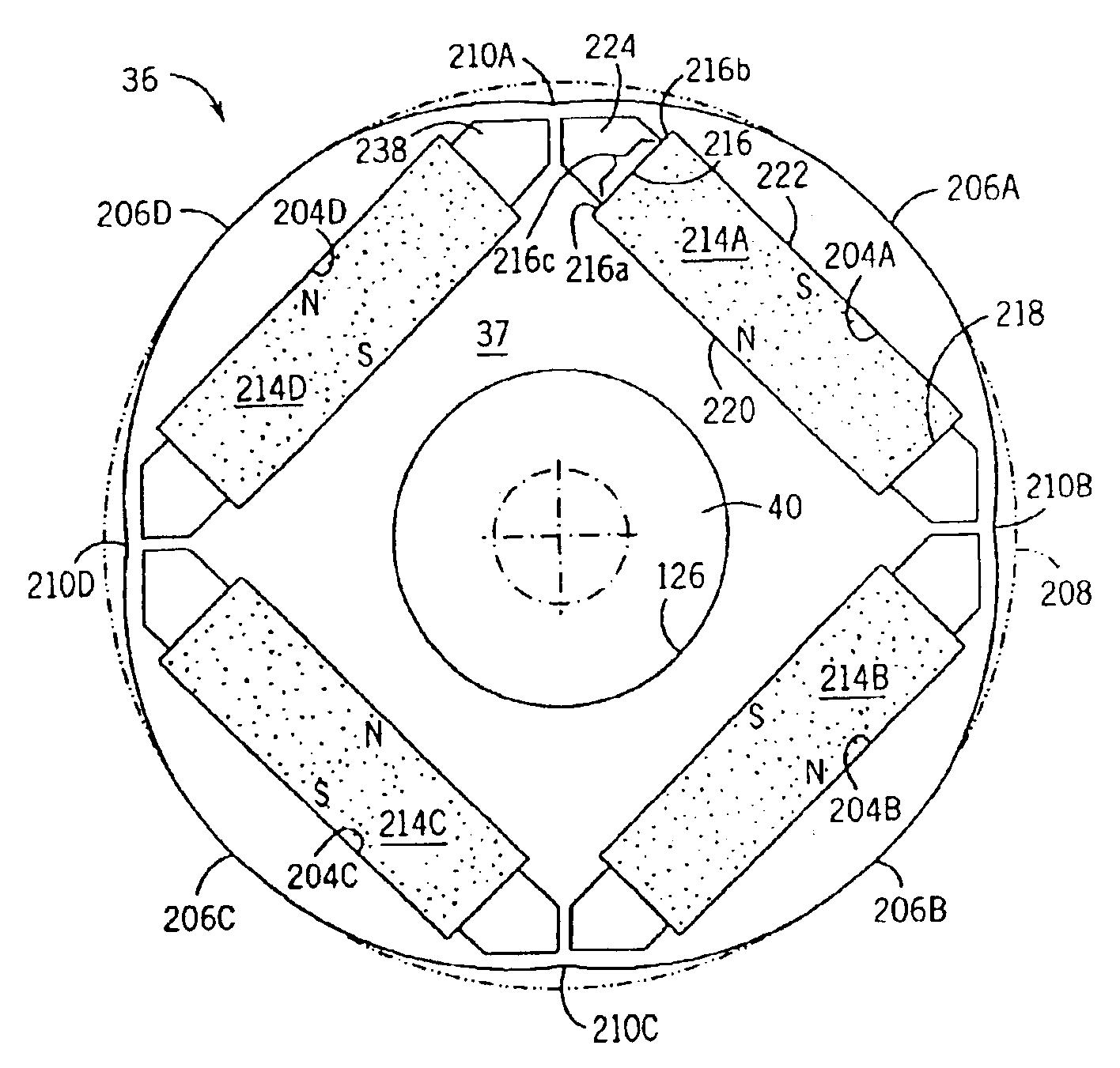
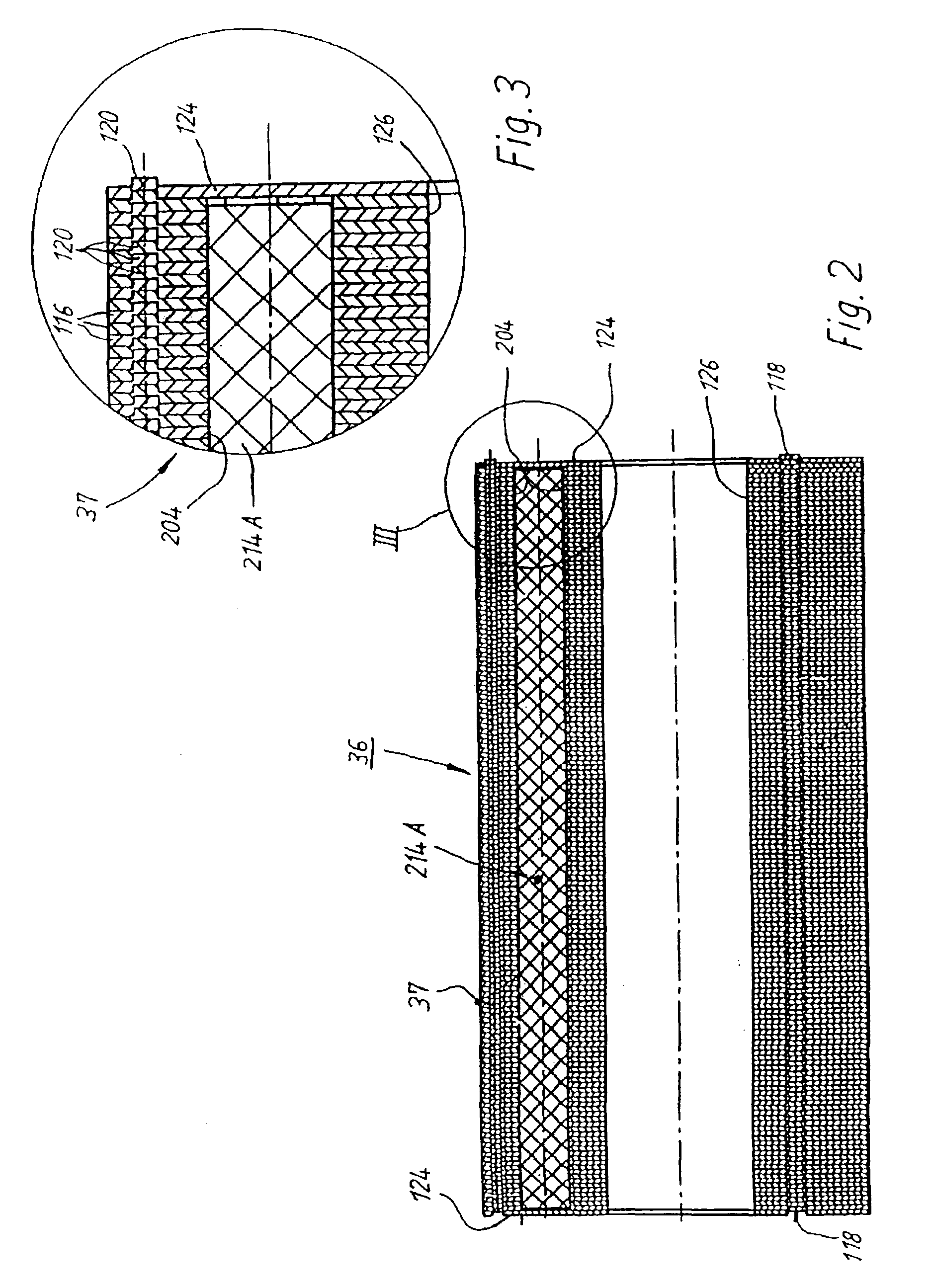
[0026]In the cylindrical housing portion 24, there is arranged the lamination stack 128 (FIG. 9) of an external stator 28 whose winding heads are designated 30 and 32. Stator 28 has an internal recess 34, in which the rotor is received. The rotor is a four-pole internal rotor 36 with a lamination stack 37 of electrical steel, preferably alloy V400, and permanent magnets 214A through 214D (Cf. FIGS. 9-11). Rotor 36 is arranged on a shaft 40, whose drive end is designated 42 and whose inner end is designated 44. An air gap 39 separates stator 28 from rotor 36. Such a motor can be called a “permanently excited synchronous internal rotor machine.”

[0027]In the A-side bell 26, in the usual manner, a seal 46 is provided for the shaft 40. Also there is a recess 48, into which is placed a guide element 50 for the outer r...


PUM


Abstract

A low-ripple multi-phase internal rotor motor has a slotted stator (28) separated by an air gap (39) from a central rotor (36). The rotor has a plurality of permanent magnets (214), preferably neodymium-boron, arranged in pockets (204) formed in a lamination stack (37), thereby defining a plurality of poles (206) separated by respective gaps (210). In a preferred embodiment, the motor is three-phase, with four rotor poles and six stator poles. As a result, when the first and third rotor poles are so aligned, with respect to their opposing stator poles, as to generate a reluctance torque, the second and fourth rotor poles are aligned to generate oppositely phased reluctance torques, so that these torques cancel each other, and essentially no net reluctance torque is exerted on the rotor. In order to magnetically separate the rotor magnets from each other, a hollow space (224, 238) is formed at the interpolar-gap-adjacent end face (216, 218) of each rotor magnet. A control circuit (147) provides electronic commutation and current control, based on rotor position signals generated with the aid of a control magnet (110) on the rotor shaft (40).

Description

FIELD OF THE INVENTION[0001]The present invention relates generally to a multiphase internal rotor motor with a slotted stator and a permanent magnet rotor.BACKGROUND[0002]In such motors, the phenomenon occurs that the boundaries between the individual rotor poles, the so-called “pole boundaries,” seek the positions of the largest air gaps. For the observer, this has the appearance that the pole boundaries are attracted by the slots of the stator. This effect is called “cogging.” The torque created thereby is called “cogging torque” because it seeks to hold the rotor in particular rotational positions, or arrest it as it passes through those positions.[0003]This effect is generated by a so-called “reluctance torque,” i.e. during the rotation of the rotor, relative to the stator, in the magnetic circuit of the motor, in certain rotation angle ranges, magnetic energy is stored, and, in other rotation angle ranges, this magnetic energy is released, analogous to when one alternately ten...

Claims


Application Information

Patent Timeline
IPC IPC(8): H02K1/27
CPCH02K1/276
Inventor ILES-KLUMPNER, DORIN
Owner EBM PAPST ST GEORGEN & -
Why Eureka
Try Eureka