Compact low-pressure discharge lamp

a low-pressure discharge lamp, compact technology, applied in the direction of electric discharge lamps, discharge tubes luminescnet screens, coupling device connections, etc., can solve the problem of relatively high production costs of compact low-pressure discharge lamps, and achieve the effect of simple change during production

Inactive Publication Date: 2005-07-19
PATENT TREUHAND GESELLSCHAFT FUR ELECTRIC GLUEHLAMPEN MBH
View PDF7 Cites 9 Cited by
  • Summary
  • Abstract
  • Description
  • Claims
  • Application Information

AI Technical Summary

Benefits of technology

[0017]The optional configuration of the further mount as an enveloping bulb, reflector or closure cap makes it simple during production to change from compact low-pressure discharge lamps without

Problems solved by technology

The production costs for such compact low-pres

Method used


Image

  • Compact low-pressure discharge lamp
  • Compact low-pressure discharge lamp
  • Compact low-pressure discharge lamp

Examples


Embodiment Construction

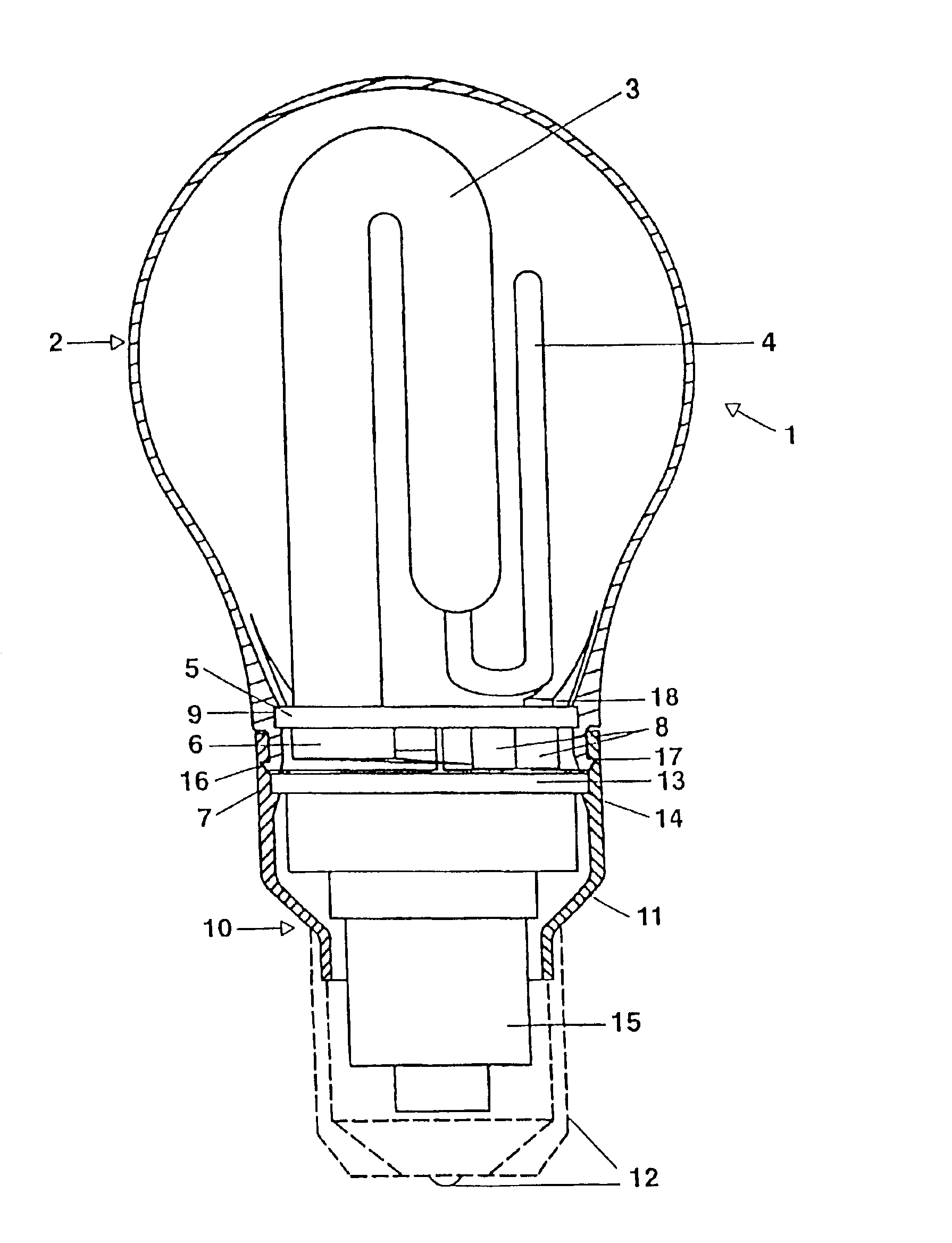
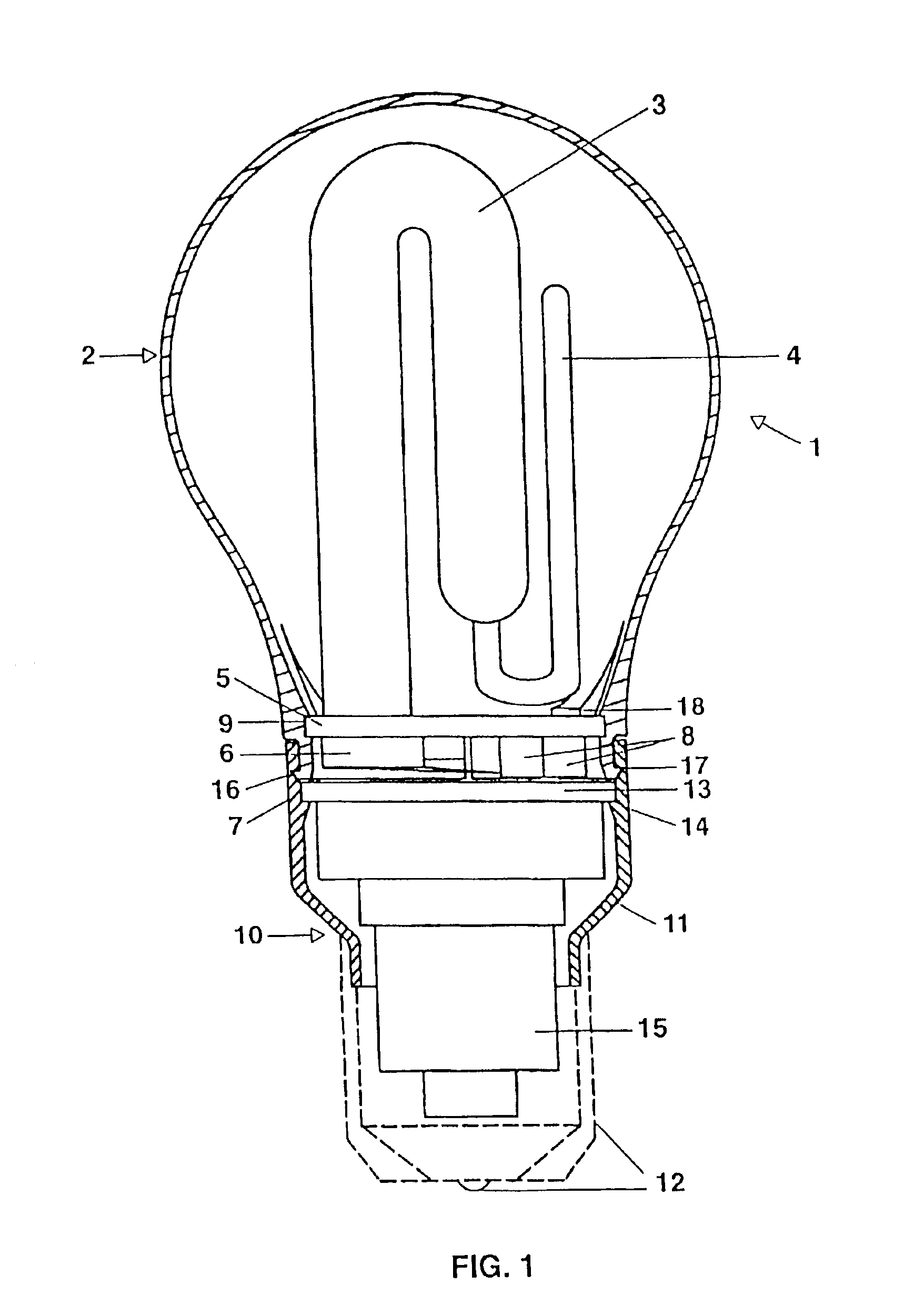
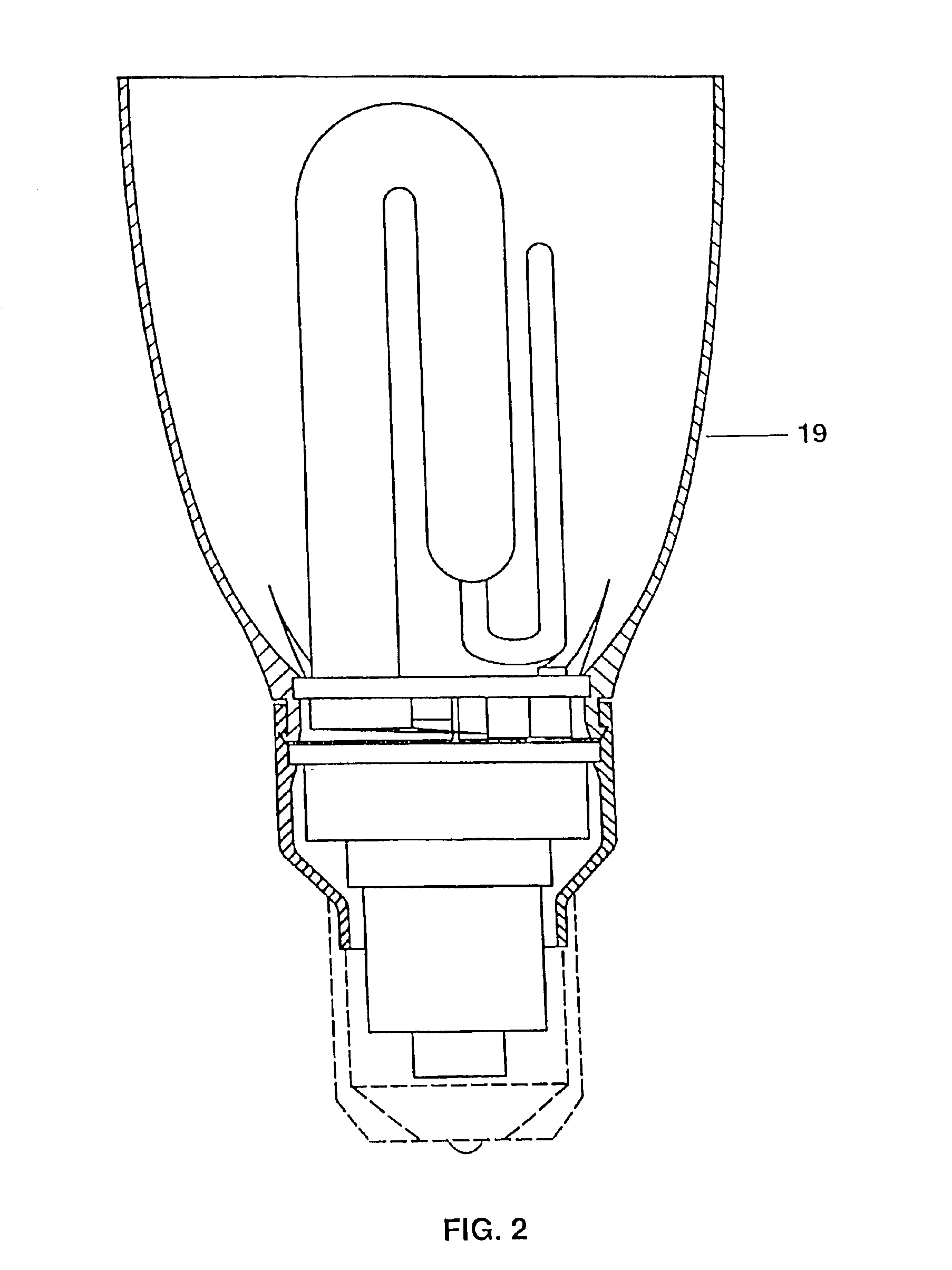
[0022]FIG. 1 shows a sectioned side view of a compact low-pressure discharge lamp 1 according to the invention having an enveloping bulb 2. The lamp has a discharge vessel 3 which is wound a number of times and has an amalgam filling, with which the pump tube 4 is filled. The ends of the discharge vessel are pushed into apertures in a mounting plate 5 composed of plastic, and are mounted by means of cap cement (which cannot be seen here) in the surrounding edge 6, which is in the form of a bead, of the apertures. The electrodes, which are fused into the ends of the discharge vessel 3, are connected via power supply leads 7 to contacts, which are mounted by means of holders 8 on the mounting plate 5.

[0023]The edge of the mounting plate 5 is snapped into a circumferential groove 9 on the inner wall of the enveloping bulb 2.

[0024]The low-pressure discharge lamp 1 also has an essentially cylindrical cap 10 with a housing 11 and schematically illustrated connecting contacts 12. A mountin...


PUM


Abstract

The invention relates to a compact low-pressure discharge lamp (1) comprising a discharge vessel (3) with electrodes and power supply leads (7), a discharge vessel mount on which the discharge vessel is mounted, and a cap (10), which comprises a housing (11), connecting contacts (12) and a mounting plate (13) with a ballast apparatus (15), with the mounting plate being fitted with the ballast arrangement in the interior of the cap housing, and having connections for electrical connection of the mounting plate to the power supply leads and to the connecting contacts. The discharge vessel mount in this case comprises a plate (5) which is mounted in a further mount, with the further mount in turn being mounted on the housing of the cap. The further mount may be in the form of an enveloping bulb (2) or a reflector for the discharge vessel, or in the form of a closure cap (20) for the cap housing.

Description

TECHNICAL FIELD[0001]The invention relates to a compact low-pressure discharge lamp comprising a discharge vessel with electrodes and power supply leads, a discharge vessel mount on which the discharge vessel is mounted and a cap, which comprises a housing, connecting contacts and a mounting plate with a ballast arrangement, with the mounting plate being fitted with the ballast arrangement in the interior of the cap housing, and having connections for electrical connection of the mounting plate to the power supply leads and to the connecting contacts.BACKGROUND ART[0002]Low-pressure discharge lamps such as these may also be provided with a reflector or an enveloping bulb. For relatively high wattages, the discharge vessel in this case comprises a tube which is composed of one or more pieces and is bent a number of times, and which is held in the housing with the aid of a mount part, whose shape is complex and which is composed of plastic or metal. One example of this is described in...

Claims


Application Information

Patent Timeline
IPC IPC(8): H01J61/00H01J61/34H01J5/00H01J61/30H01J61/56H01J61/32H01J61/36H01J61/70H01J61/02H01J5/54H01J9/34H01J1/62H01J1/00H01J5/48H01J5/58
CPCH01J5/48H01J5/54H01J5/58H01J61/327
Inventor BACHETZKY, BRUNOJAKOB, ANDREASNOLL, THOMAS
Owner PATENT TREUHAND GESELLSCHAFT FUR ELECTRIC GLUEHLAMPEN MBH
Why Eureka
Try Eureka