Tuned perturbation cone feed for reflector antenna

a reflector antenna and cone feed technology, applied in the direction of antennas, waveguide horns, electrical equipment, etc., can solve the problems of introducing some loss in operating efficiency, increasing the overall weight of the shield, wind load, structural support and manufacturing costs of the antenna, and affecting the effect of the

Inactive Publication Date: 2005-07-19
COMMSCOPE TECH LLC
View PDF8 Cites 62 Cited by
  • Summary
  • Abstract
  • Description
  • Claims
  • Application Information

AI Technical Summary

Benefits of technology

[0059]The sub-reflector surface 5 and a leading cone surface 30 (facing the dish reflector 3) of the sub-reflector assembly 1 may have a plurality of concentric non-periodic perturbation(s) 35 in the form of corrugations, ridges and protrusions of varied heights, depths and or widths. Internal, external and combinations of internal and external perturbations may be applied. Also, a leading angle selected for pattern and VSWR matching between the waveguide junction portion 15 and a first perturbation, along the leading cone surface 30, may then change as the leading cone surface 5 continues to a periphery of the subreflector assembly 1, for example as shown on FIG. 13a. Where the prior art may have utilized a single perturbation for VSWR matching purposes, the present invention utilizes multiple perturbations to control internal reflections and thereby form a desired radiation pattern. Calculated using a full wave solution with the assistance of commercially available full wave RF radiation pattern calculation software rather than ray tracing, the location and specific dimensions of the perturbations and angle changes may be calculated and then further iteratively adjusted to minimize multi-path reflections within the dielectric material, control amplitude and phase distribution from the feed and improve the impedance match (VSWR) between the feed and free space.
[0062]Adapting the perturbation(s) 35 to a desired configuration provides efficiencies that previously were obtained in part by correcting the profile of the dish reflector 3. When these adaptations are made via the perturbation(s) 35, the invention provides the advantage of higher performance over a wide frequency range, for example 10-60 GHz, with the same reflector dish profile.
[0064]From the foregoing, it will be apparent that the present invention brings to the art a sub-reflector assembly 1 for a reflector antenna with improved electrical performance and significant manufacturing cost efficiencies. The subreflector assembly1 according to the invention is strong, lightweight and may be repeatedly cost efficiently manufactured with a very high level of precision.

Problems solved by technology

This configuration also facilitates the mounting of an “Outdoor Unit” comprising the initial stages of a transceiver system, directly onto the back of the main reflector and also eliminates the need for a separate feed support structure that would conventionally span the face of the main reflector, thereby introducing some loss in operating efficiency.
Shrouds however increase the overall weight, wind load, structural support and manufacturing costs of the antenna.
However such a configuration only partially resolves the internal reflections and can have a detrimental effect on both amplitude and phase radiation match between E and H planes.

Method used


Image

  • Tuned perturbation cone feed for reflector antenna
  • Tuned perturbation cone feed for reflector antenna
  • Tuned perturbation cone feed for reflector antenna

Examples


Embodiment Construction

[0055]The self-supported feed system described herein integrates the waveguide transmission line, aperture and sub-reflector into a single assembly comprising a length of waveguide, the aperture of which is terminated with a corrugated dielectric cone sub reflector assembly, the front and back surfaces of which are geometrically shaped and corrugated to provide a desired amplitude and phase radiation pattern suitable for efficient illumination of the main reflector profile.

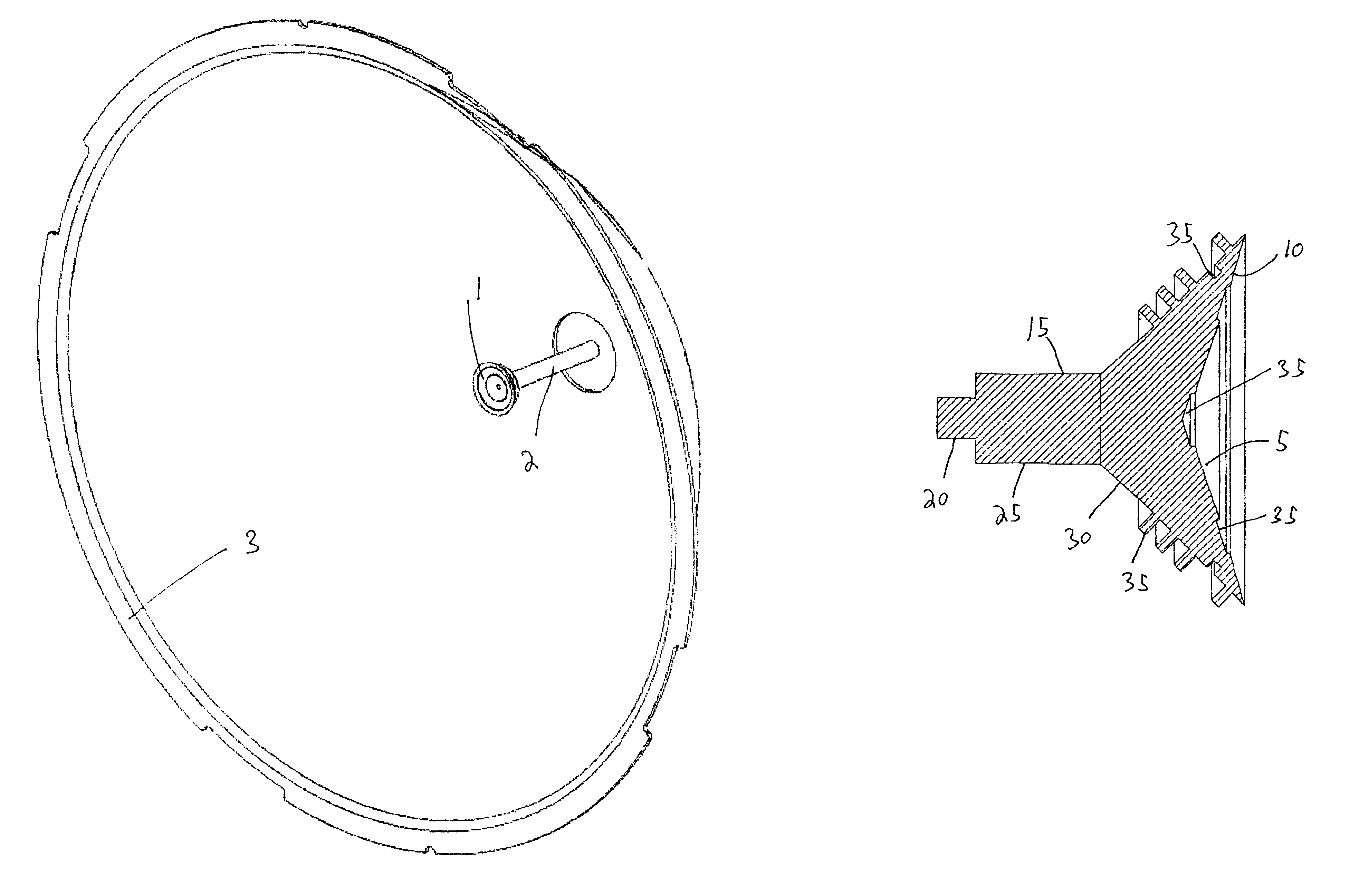
[0056]A typical dual reflector antenna according to the invention is shown in FIGS. 4a and 4b. The sub-reflector assembly 1 is mounted on and supported by a waveguide 2 to position the sub-reflector assembly 1 proximate a focal point of the dish reflector 3, here shown as a dish reflector 3 having a “deep dish” configuration.

[0057]Details of the sub-reflector 1 assembly according to the invention will now be described in detail. A first embodiment of a sub-reflector 1 according to the invention is shown in FIGS. 5...


PUM


Abstract

A sub-reflector for a dish reflector antenna with a waveguide supported sub-reflector. The sub-reflector formed from a dielectric block, concentric about a longitudinal axis. The dielectric block having a first diameter waveguide junction portion adapted for coupling to an end of the waveguide and a sub-reflector surface coated with an RF reflective material having a periphery with a second diameter larger than the first diameter. A leading cone surface extends from the waveguide junction portion to the second diameter at an angle. The sub-reflector surface and the leading cone surface having a plurality of non-periodic perturbations concentric about the longitudinal axis.

Description

BACKGROUND OF INVENTION[0001]1. Field of the Invention[0002]This invention relates to microwave dual reflector antennas typically used in terrestrial point to point, and point to multipoint applications. More particularly, the invention provides a low cost self supported feed solution for use in frequency bands between 5 GHz and 60 GHz wherein stringent regulatory standard compliance and or specific system electrical characteristics are required. The invention is particularly suited to “deep dish” designs overcoming performance limitations of prior art devices and obviating the need for a conventional shroud assembly. It is also applicable to more conventional dish profiles.[0003]2. Description of Related Art[0004]Dual reflector antennas employing self-supported feed direct a signal incident on the main reflector onto a sub-reflector mounted adjacent to the focal region of the main reflector, which in turn directs the signal into a waveguide transmission line typically via a feed ho...

Claims


Application Information

Patent Timeline
Patent Type & Authority Patents(United States)
IPC IPC(8): H01Q19/10H01Q13/00H01Q13/02H01Q19/19
CPCH01Q13/0216H01Q19/193
Inventor HILLS, CHRIS
Owner COMMSCOPE TECH LLC
Why Eureka
Try Eureka